Adrienne’s Story

Dimensional Letterforms

Jump to: Research | Concepts | Iterations | Final Reflection

My final dimensional letterforms

Twenty-six forms that represent sounds combined can create words with meaning that develop story. The visual depiction of these iconic symbols can be as simple as the scribbles of a preschooler to structural objects as seen in Lo Siento’s 4D alphabet.

Lo Siento 4D alphabet

Research

OOOOOooooooo

Both capital and lowercase letter “O”s are the same form and structure. When thinking in three dimensions, I immediately think of spheres, donuts, and targets. Taking this glyph further than extruding the surface to make a three-dimensional form is a goal.

  1. Vectorstock-circle-spherical-design-element-vector
  2. laundry-amazon
  3. www.notimeforflashcards.com
  4. Isamu Noguchi’s Skyviewing Sculpture in Red Square at Western Washington University
  5. Torus-istockphoto

Lowercase h

Or is it a chair? The stem and leg of this glyph brings ideas of architecture and furniture design. But when looking into the visual vocabulary of the lowercase “h”, I discovered how to draw a bird or to craft a house. I do love a good Old English form too.

  1. Chair + h SandroJalabadze-Dribble
  2. www.drawinghowtodraw.com
  3. www.notimeforflashcards.com
  4. logodix.com/chair
  5. Old English printableletters.org

Lowercase g

The lowercase “g” is the glyph to understand what a typeface can do for you. It’s form is versatile and unique with an ear, bowl, sometimes loop, other variants are tails. It is an obsession, just as the ampersand, to most type geeks. So much character can be derived from one character.

  1. https://qz.com “Can you recognize the letter “G”?” by Thu-Huong Ha & David Yanofsky
  2. free-printable-gothic-calligraphy-lowercase-letters-gothic-calligraphy-lowercase-G
  3. G. Ogaki Poster display typeface by Aron Jancso
  4. commons.wikimedia.org/wiki/File:G-samples
  5. The italic ampersand from Baskerville and the g from Newzald.

Back to Top

Concepts

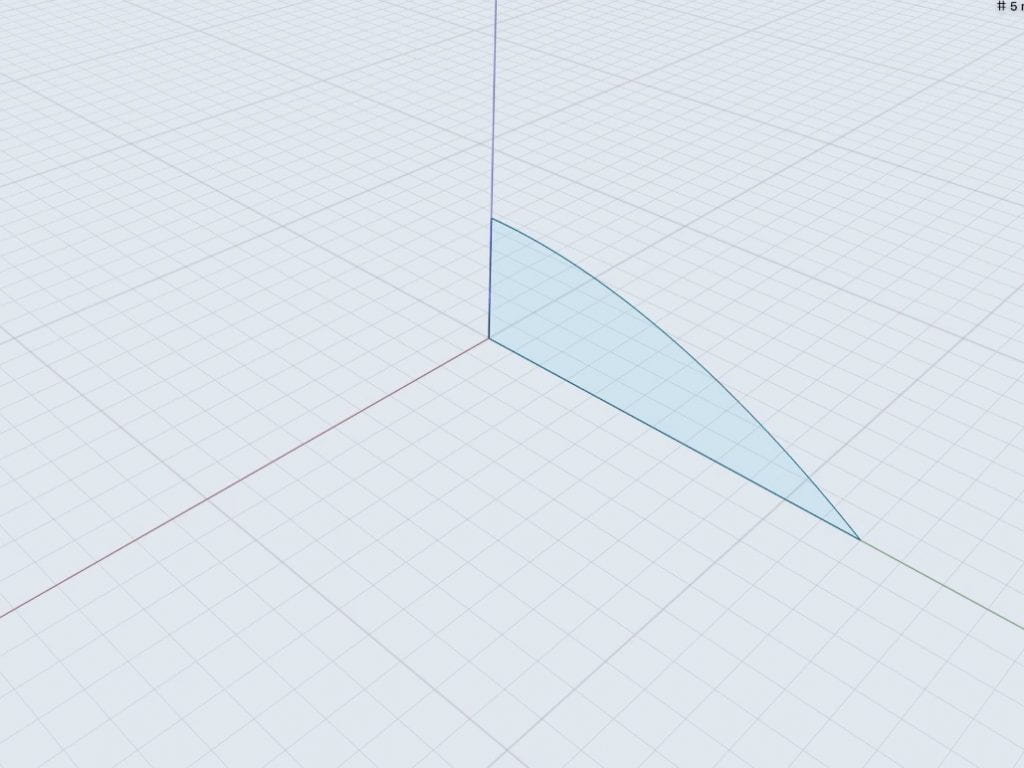
The beginning of letterform exploration in two dimension…

Sketches by Adrienne Hooker
Sketches by Rowan Wang

Back to Top

Iterations

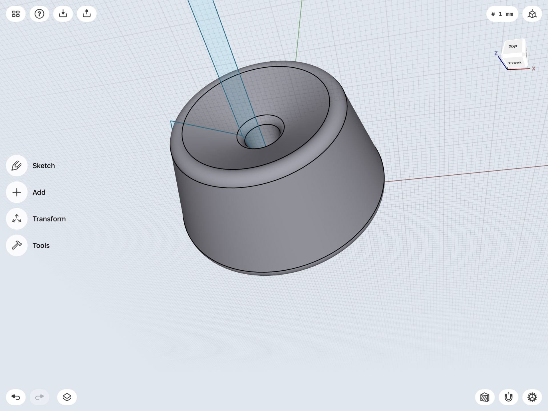
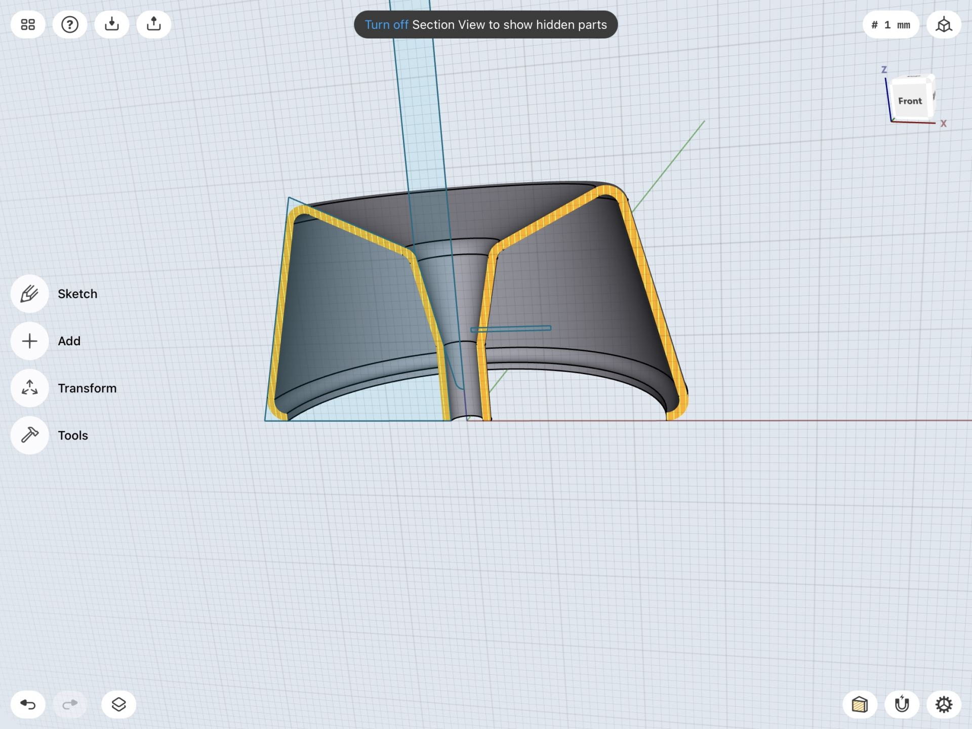
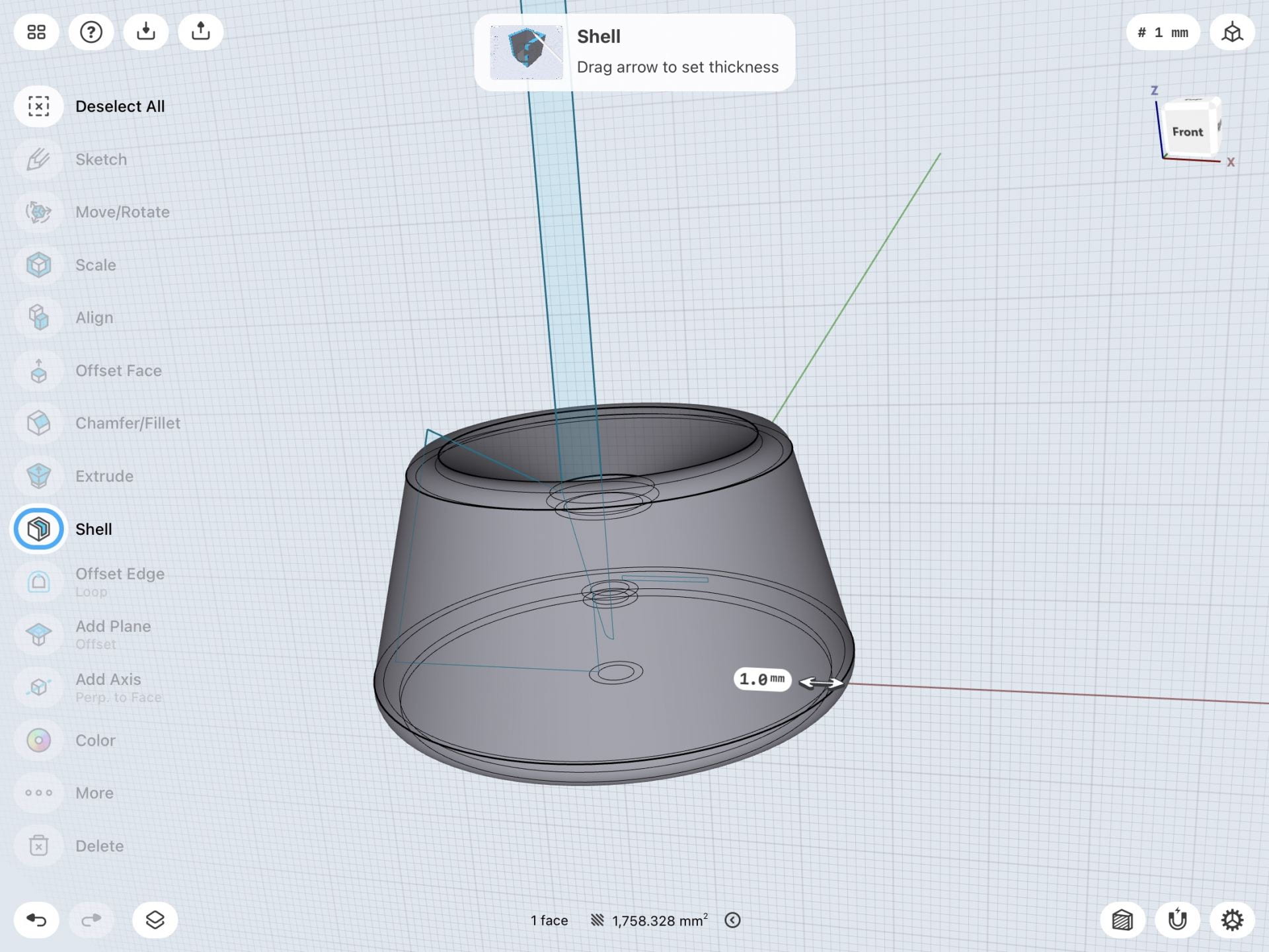
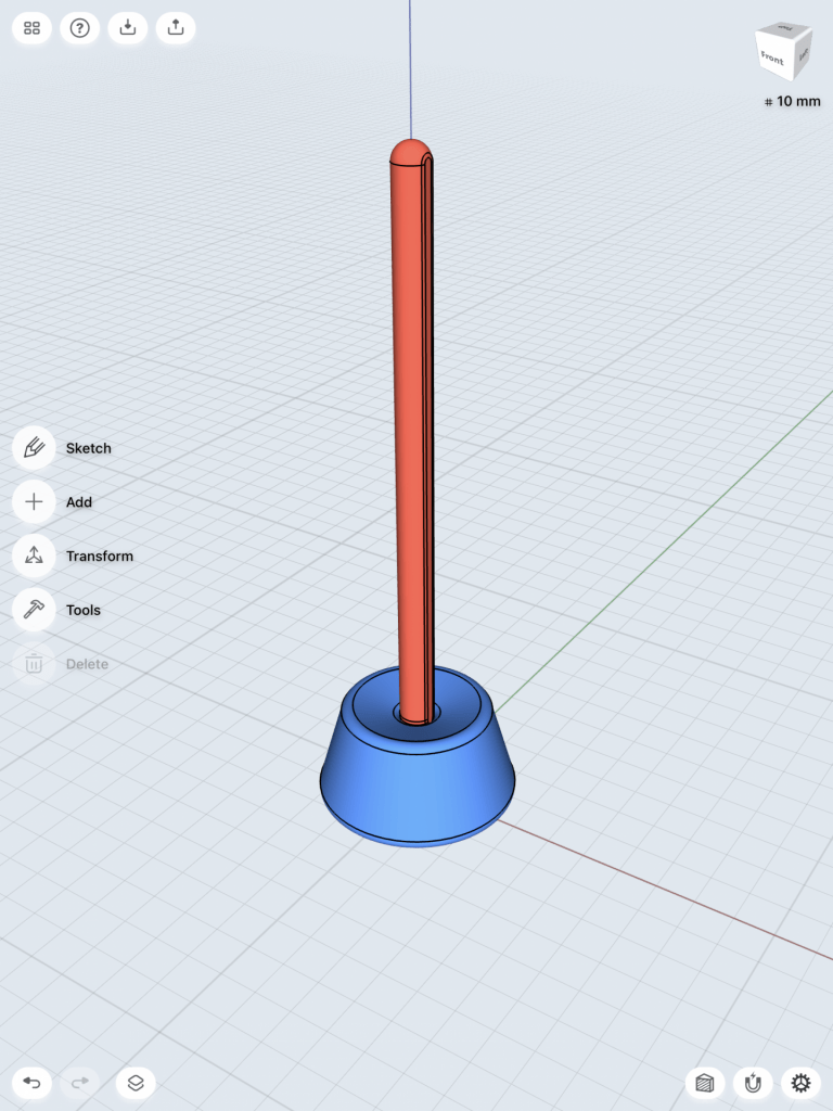
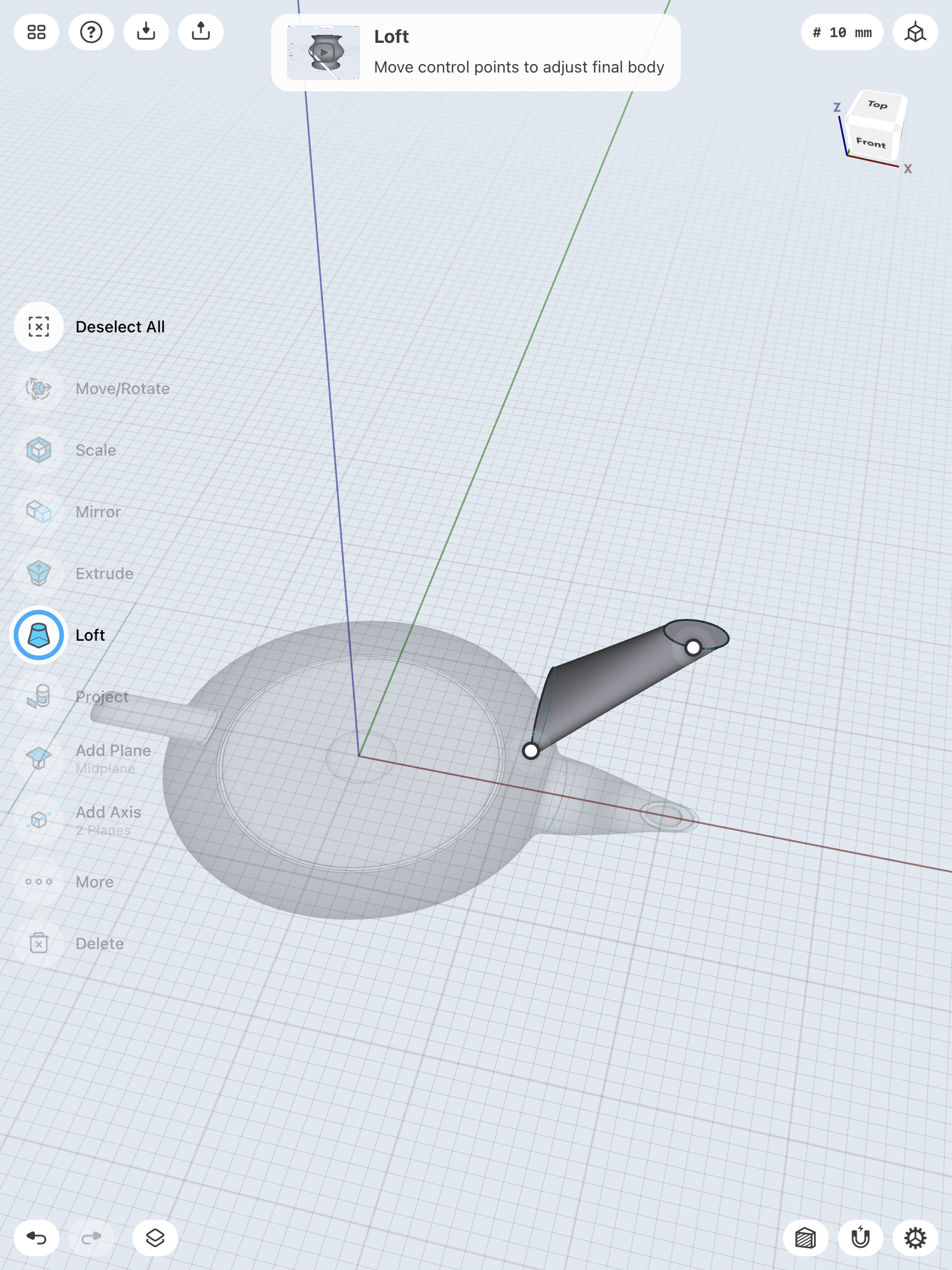
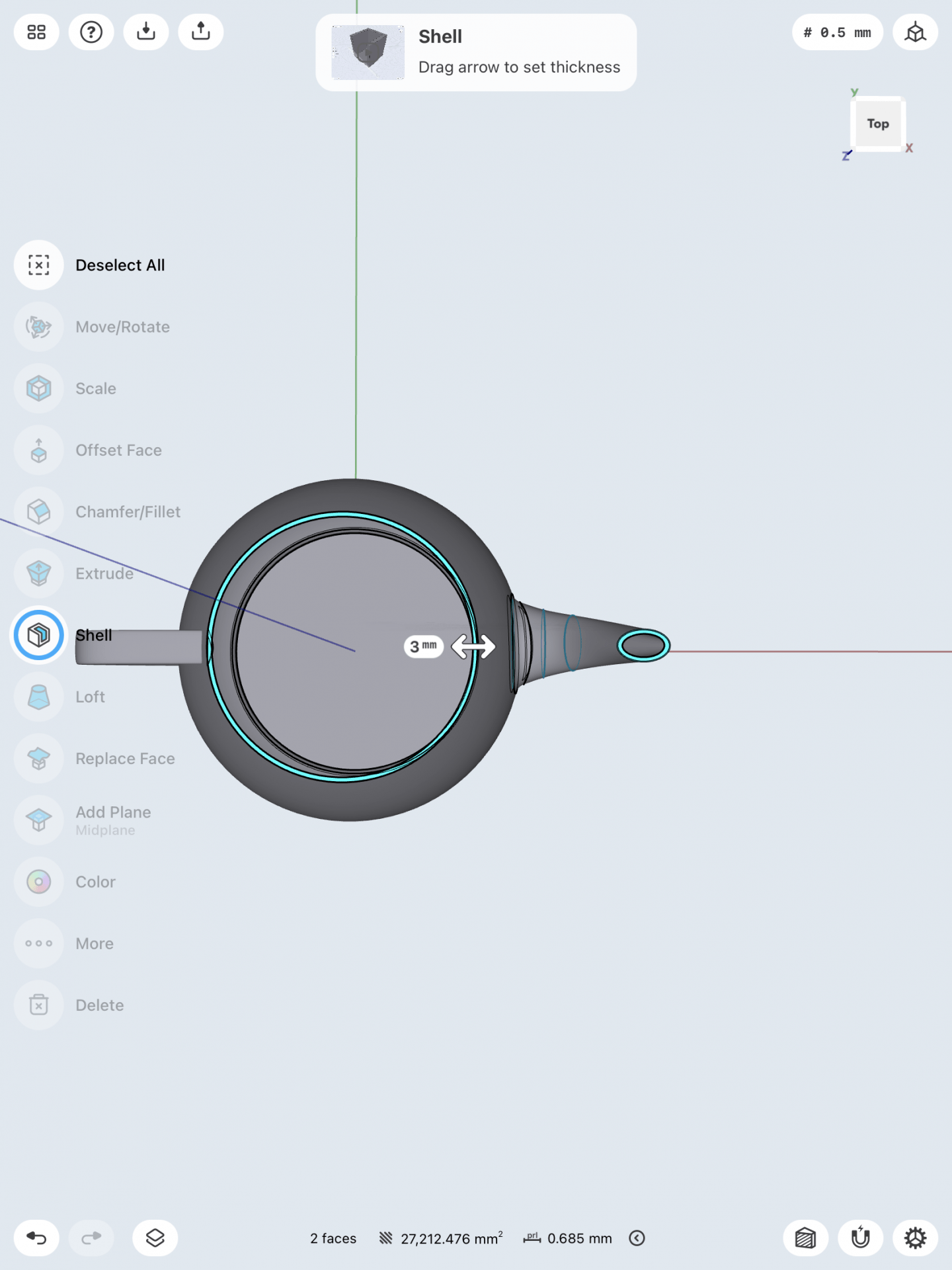
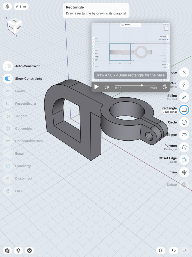
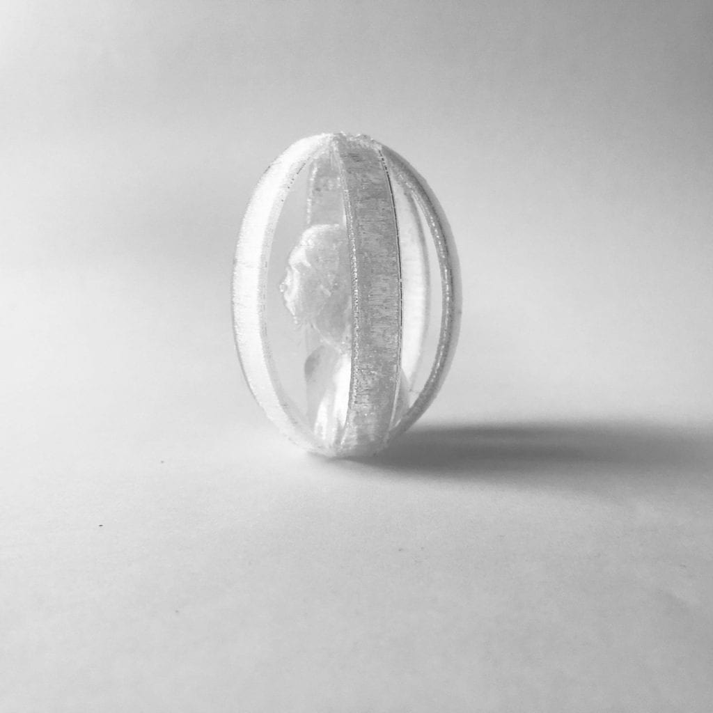
I wanted to tackle the patterned torus for the letter “O” but unfortunately time ran short so I had to settle for my oldest child, Oscar, being encased in multiple O’s. It was my first attempt at bringing in a 3D scanned model into Shapr3D and the program handled it well.

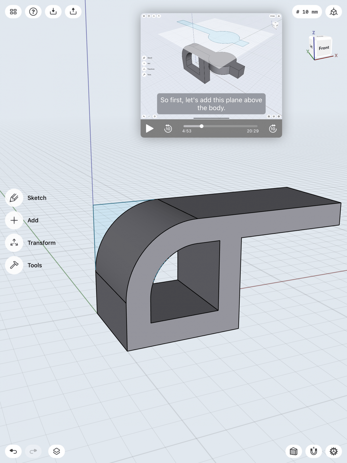
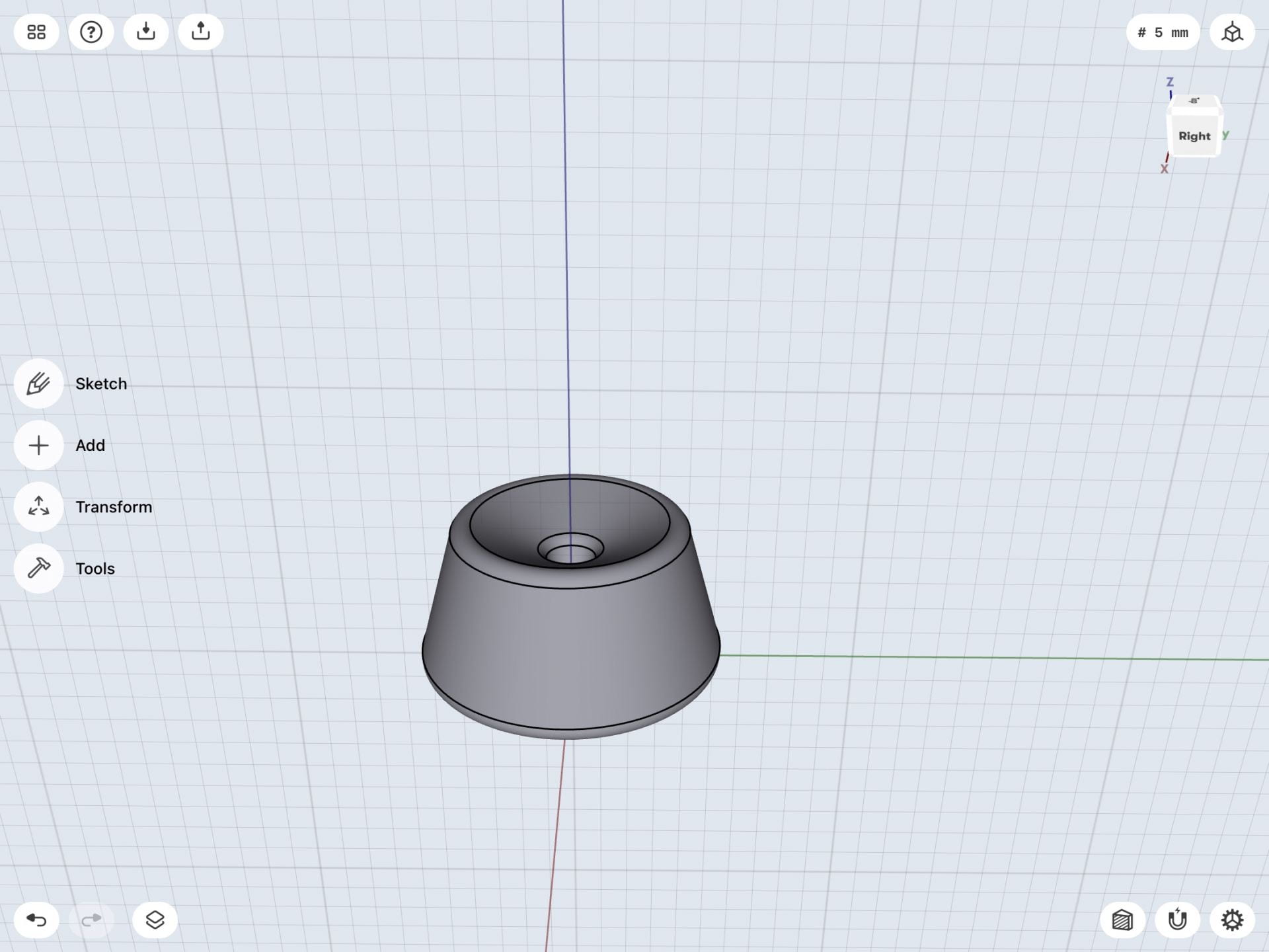
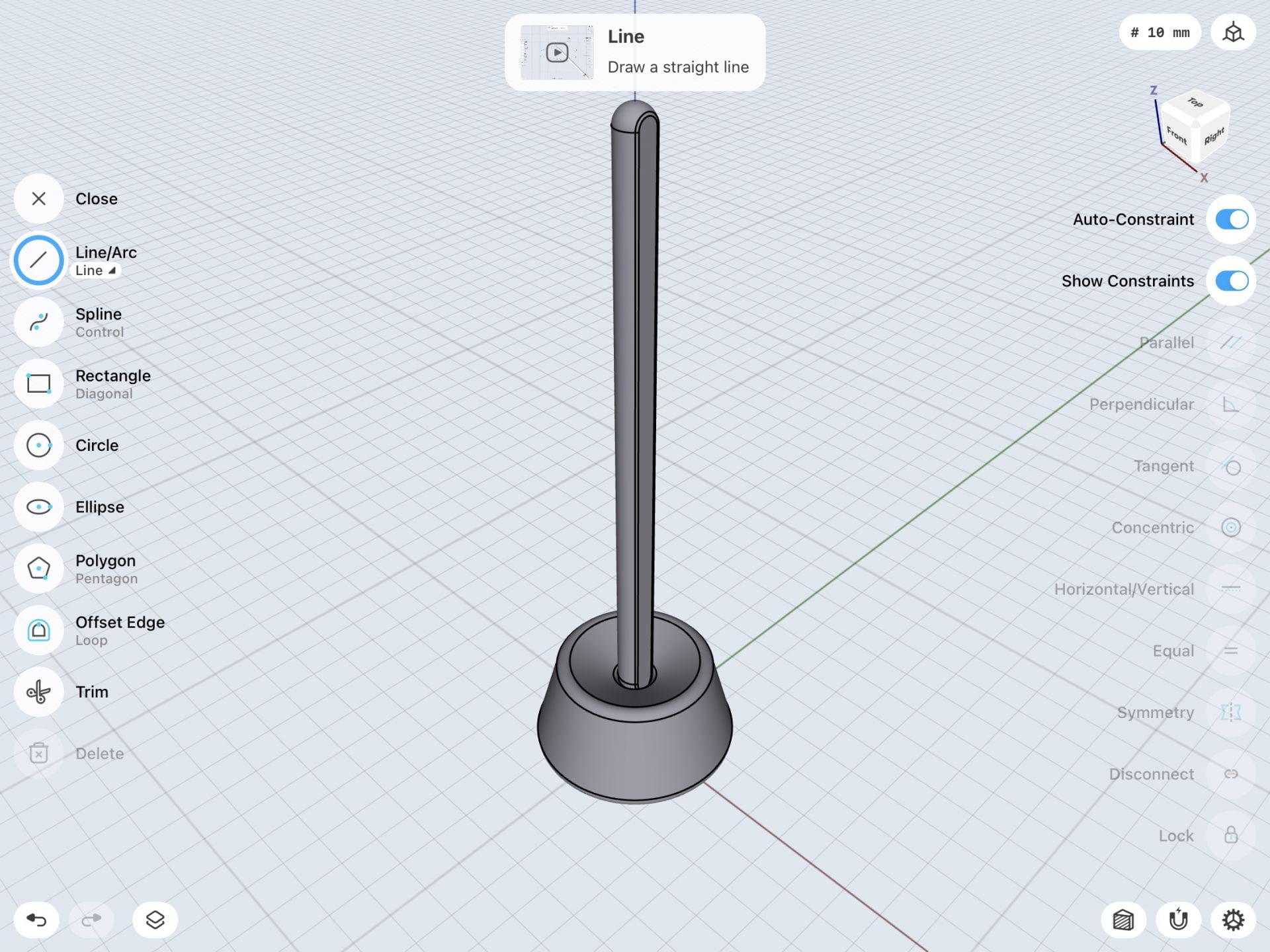
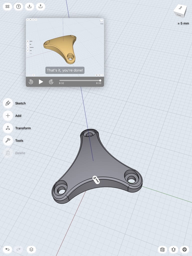
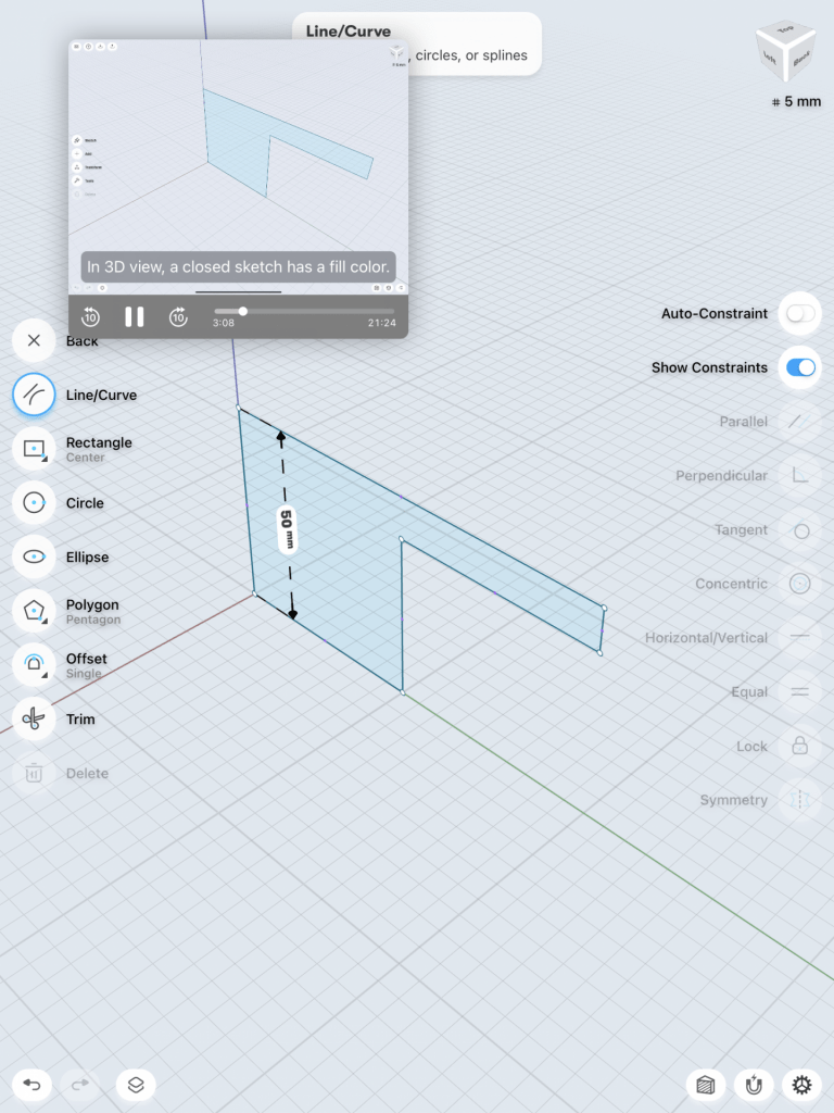
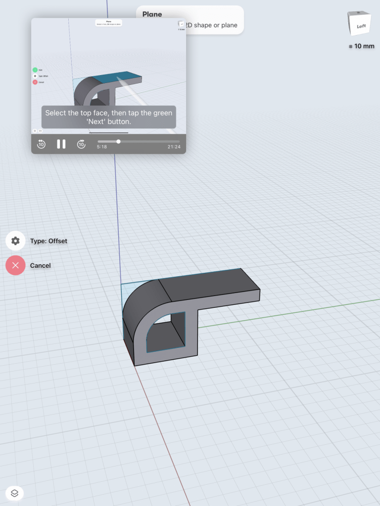
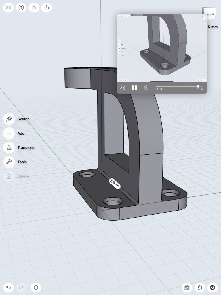
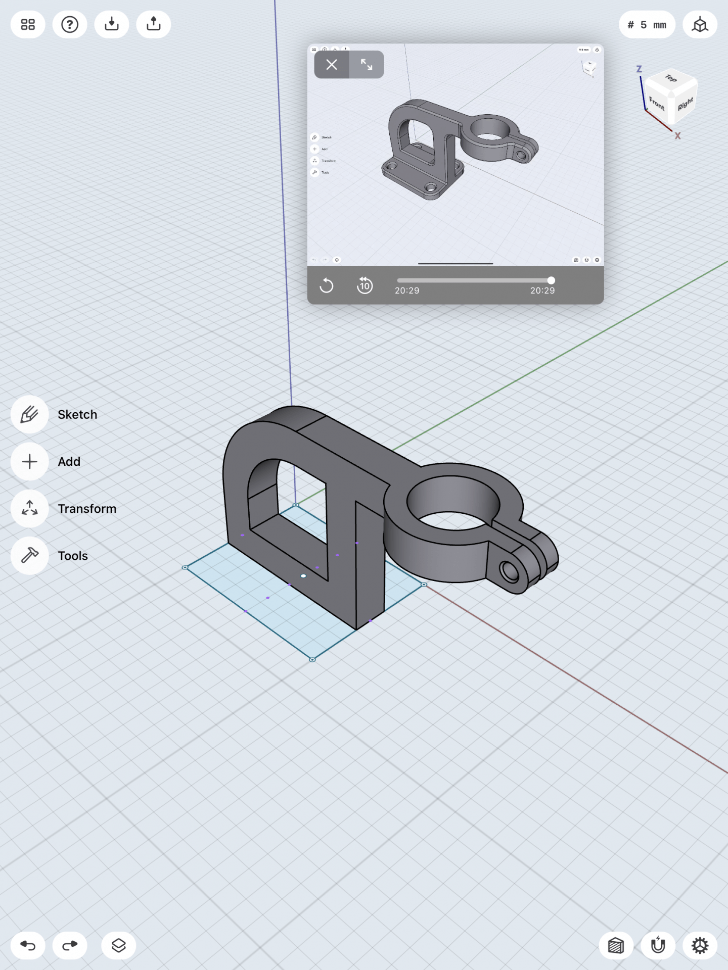
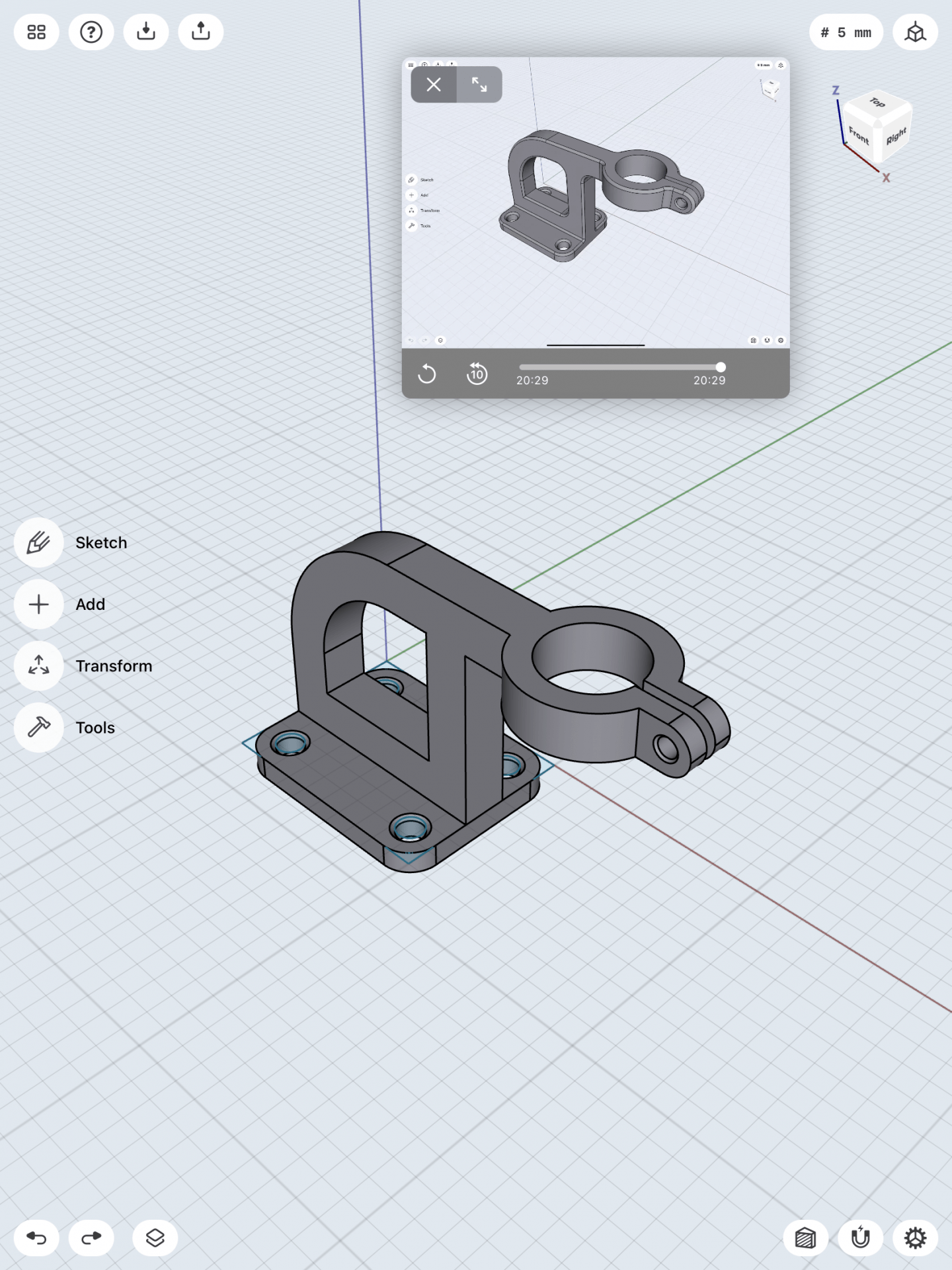
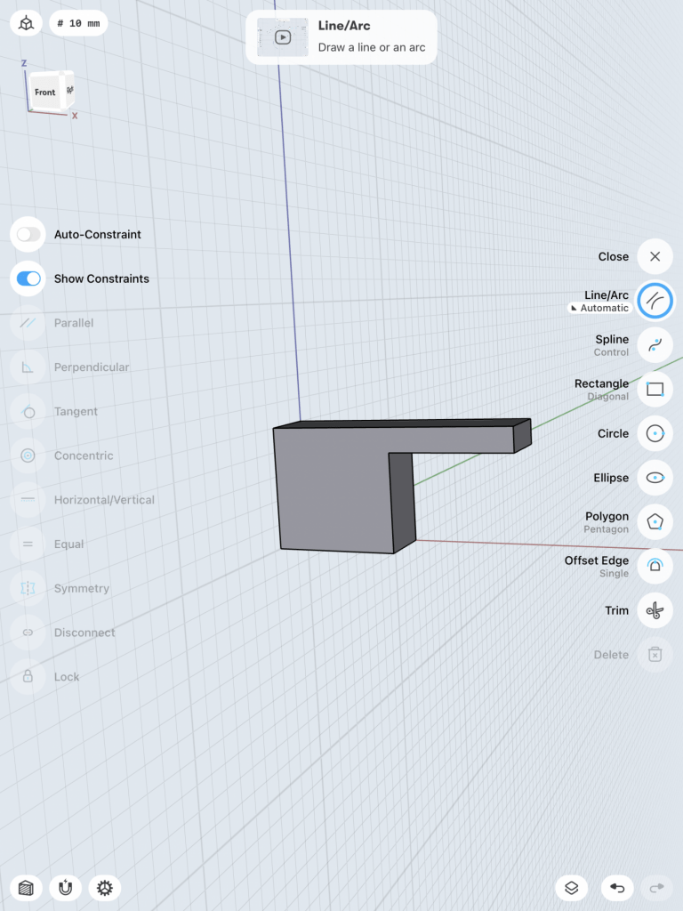
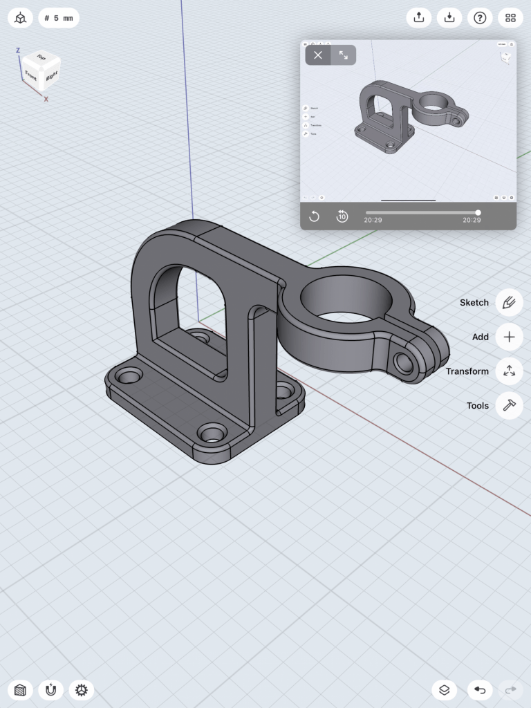
My next letterform is the lowercase “h”, fashioned after a modernist chair. It was fairly quick although a couple of the edges could be rounded better.

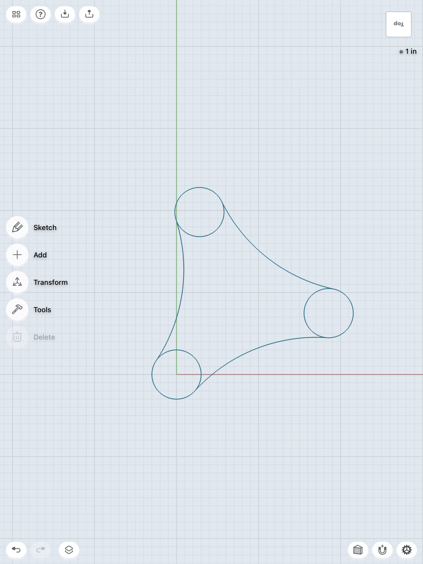
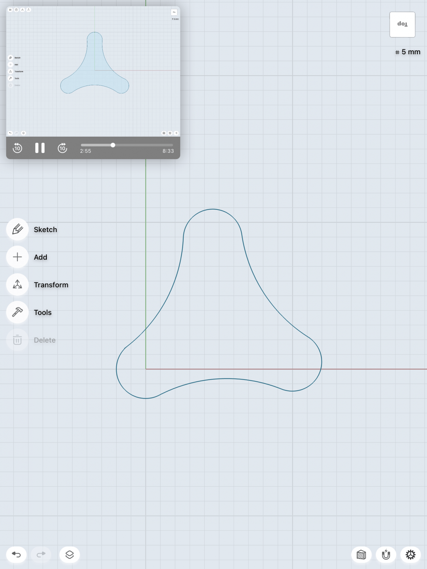
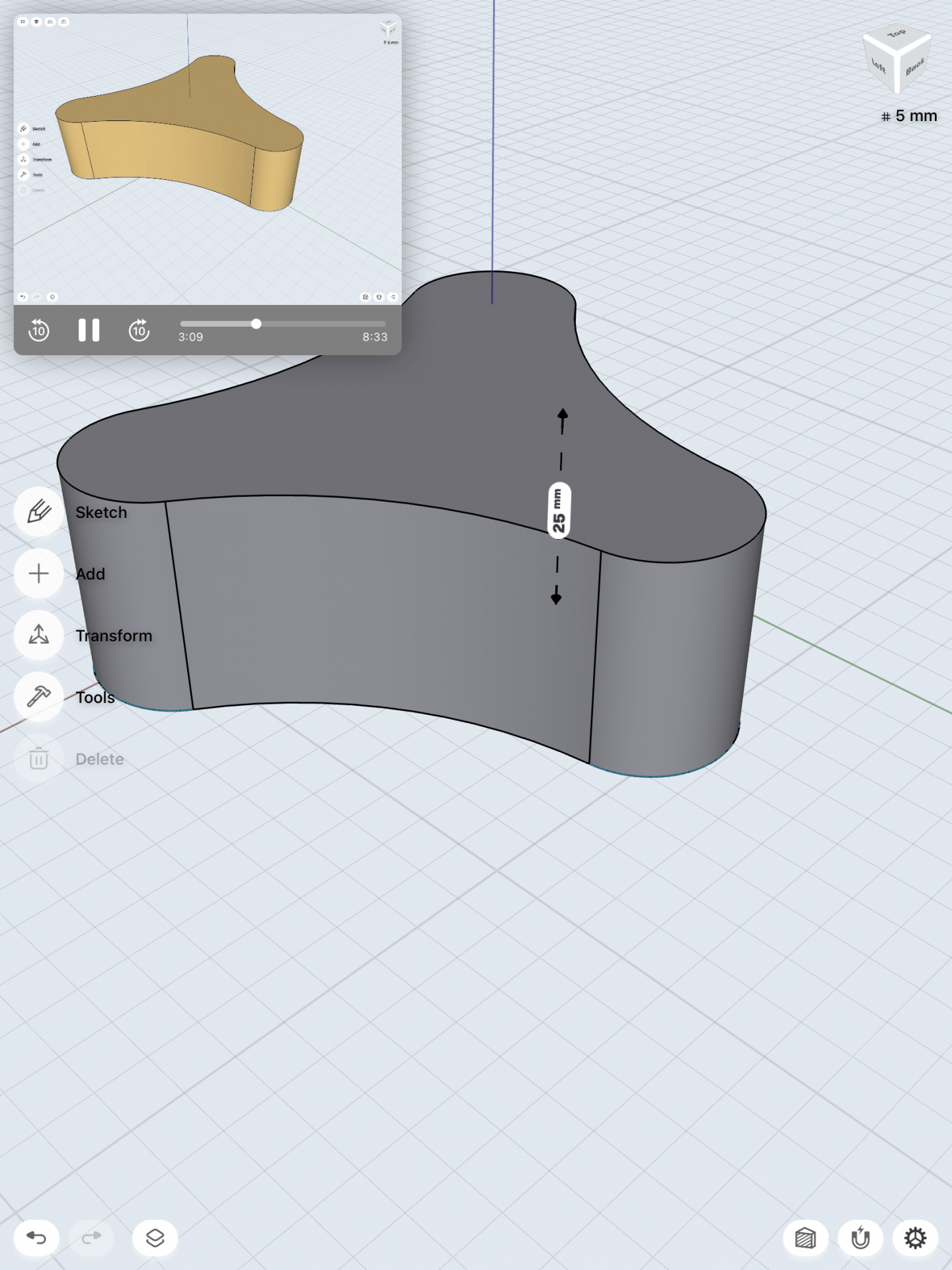
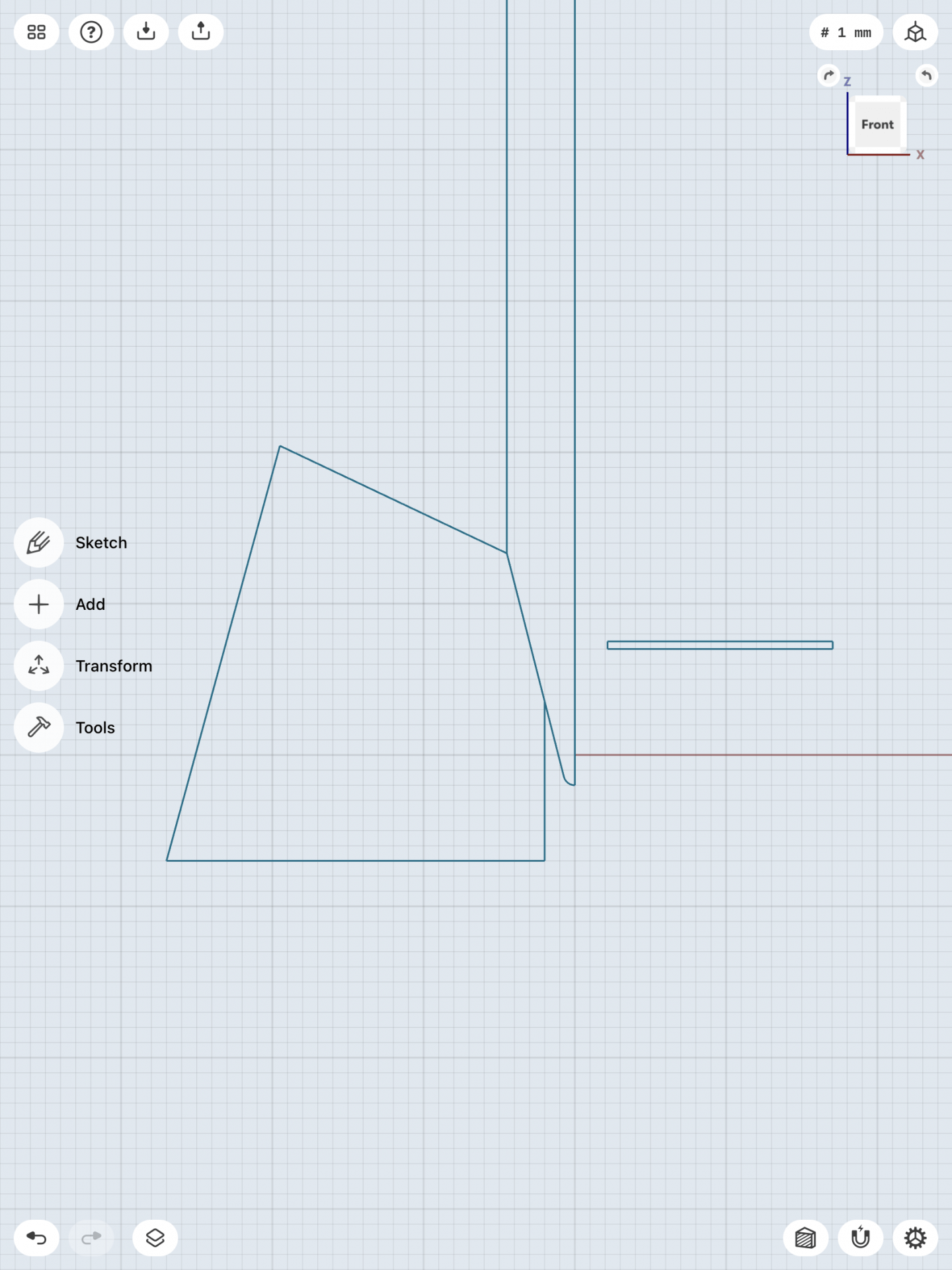
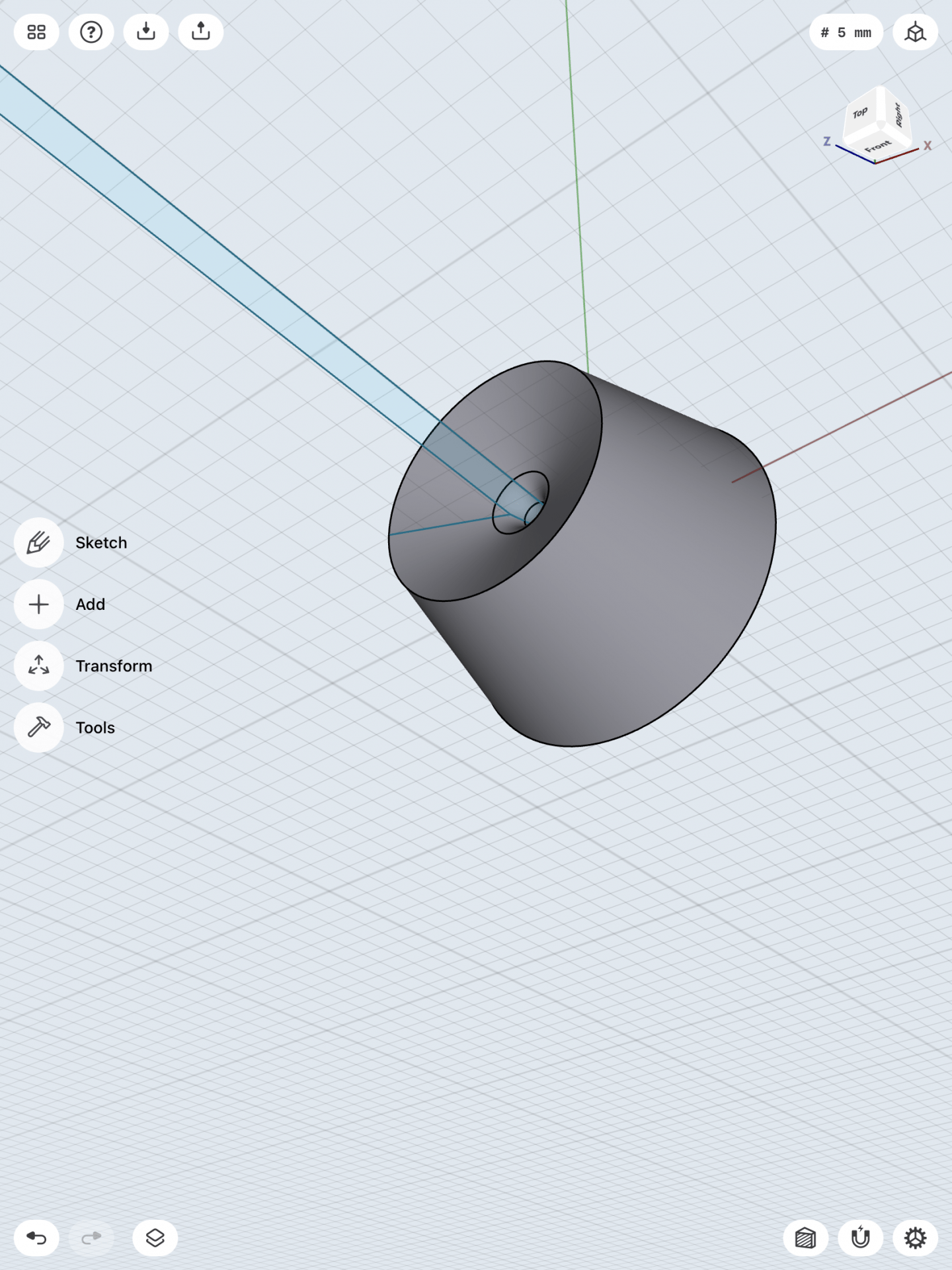
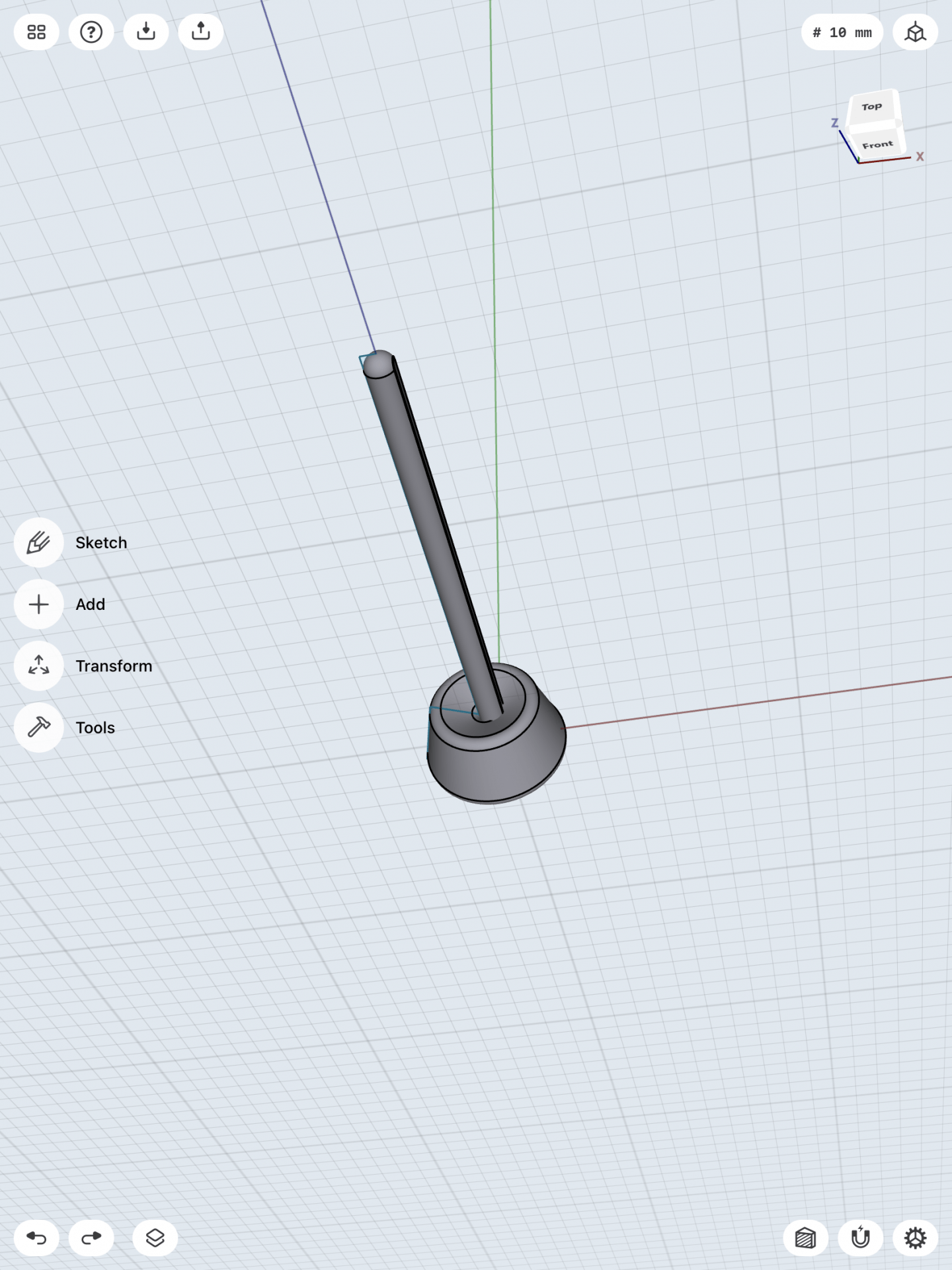
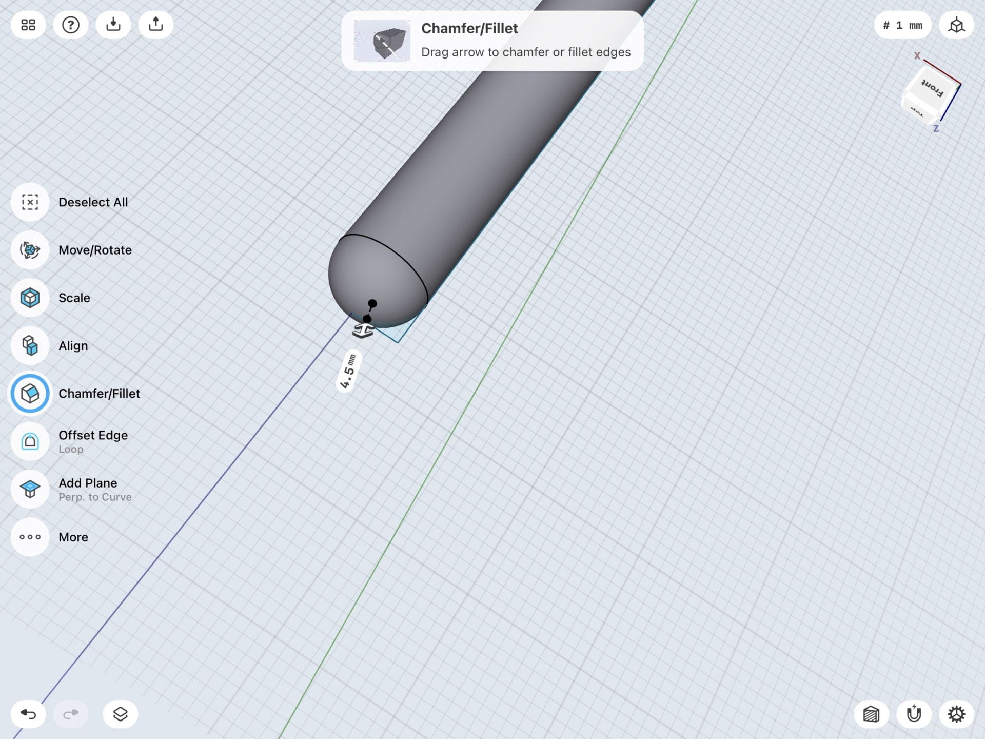
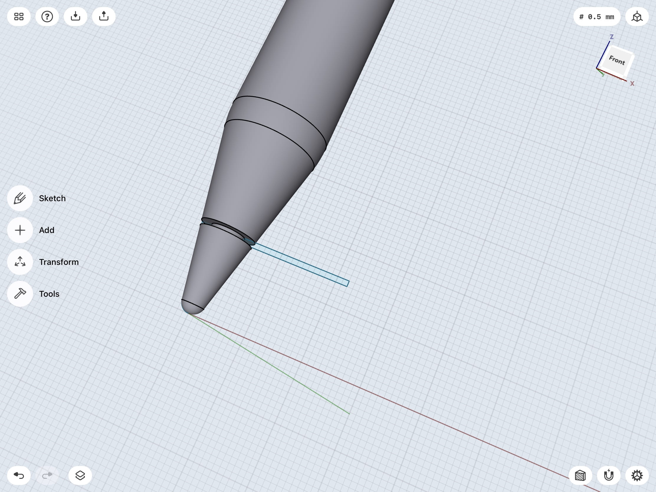
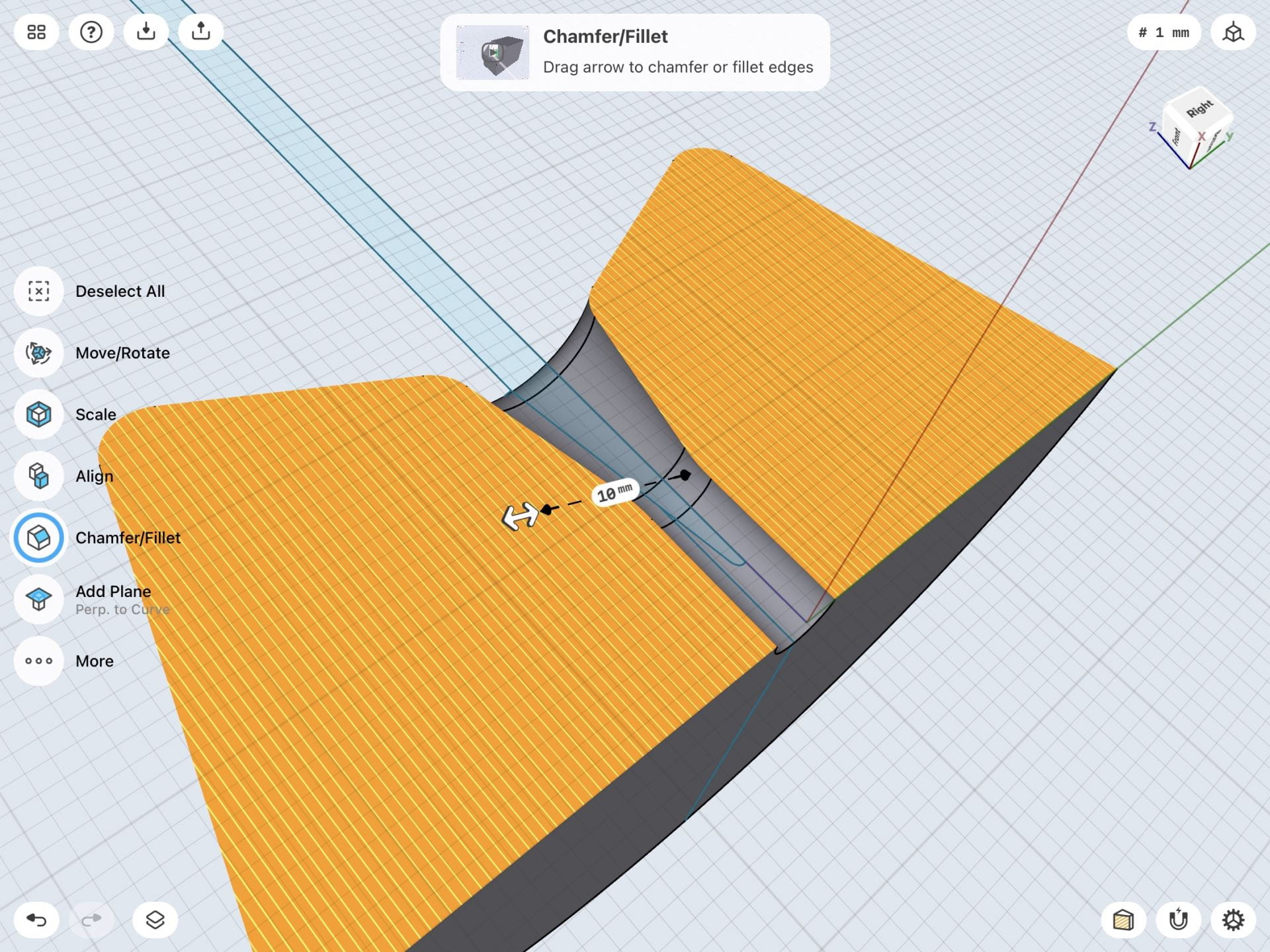
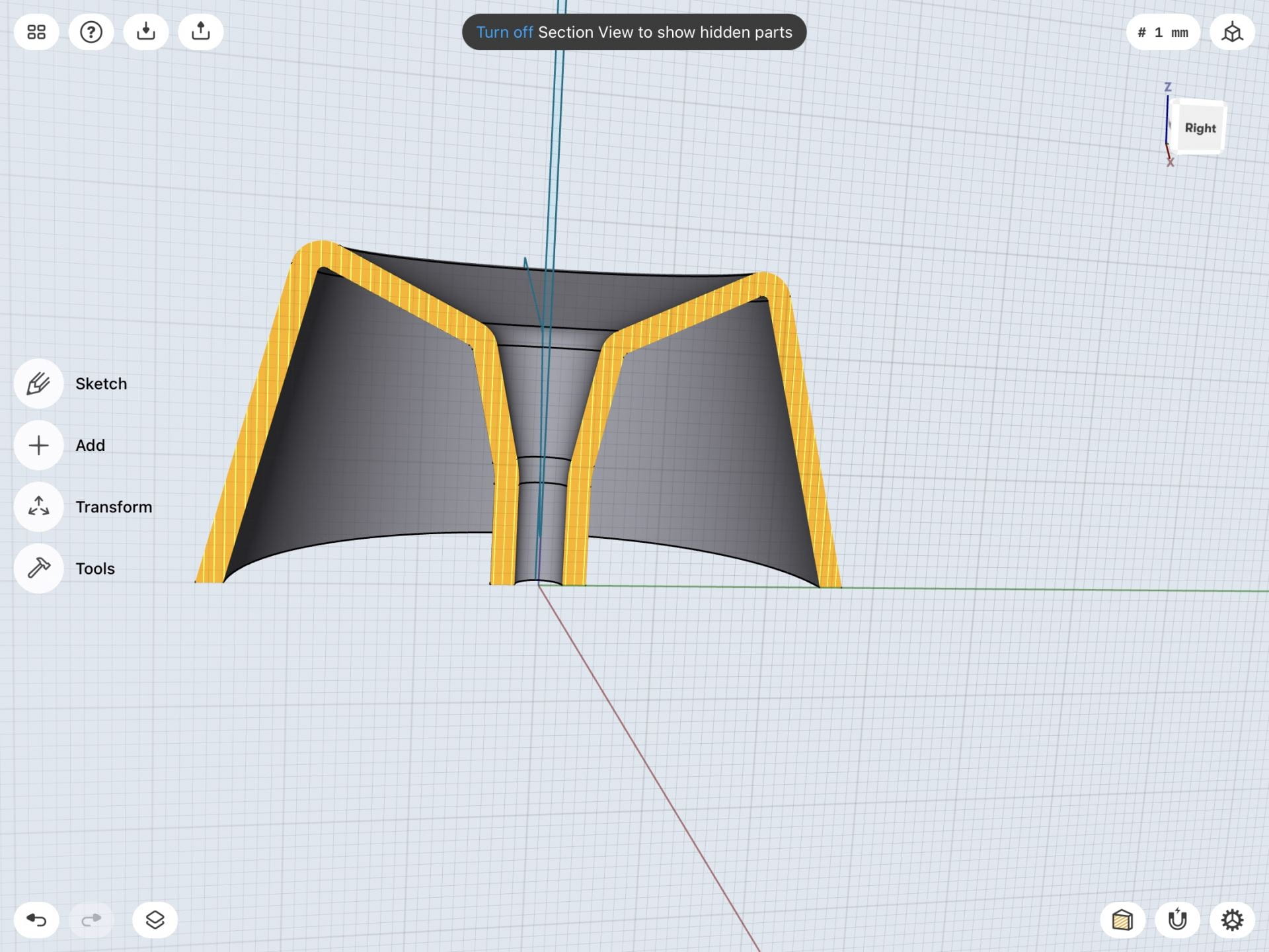
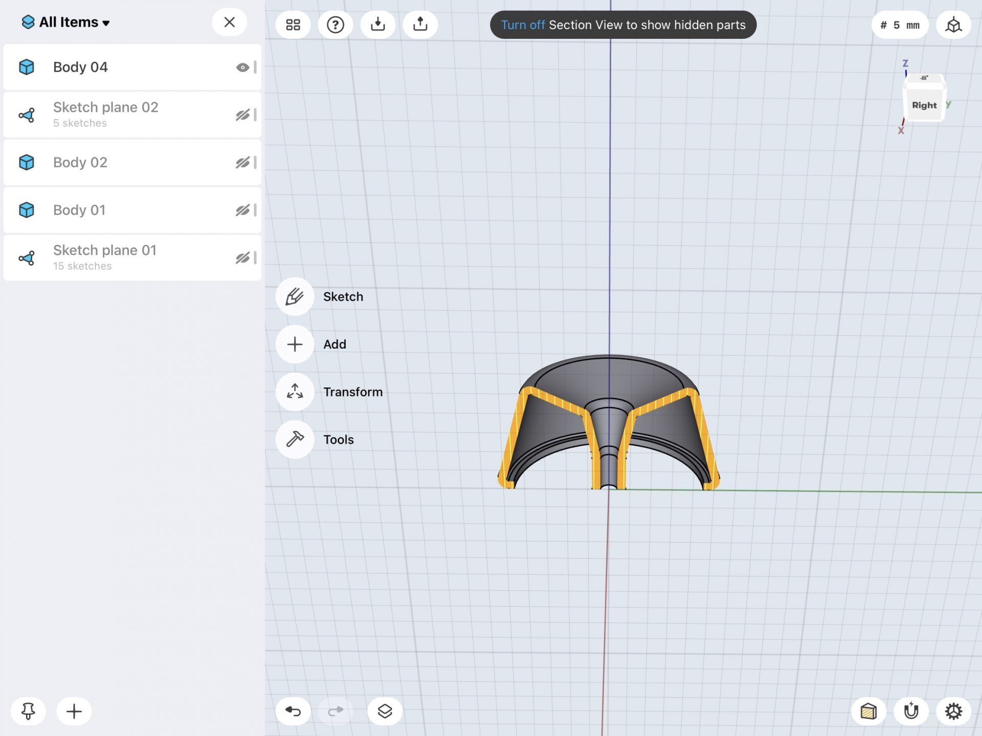
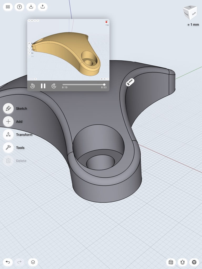
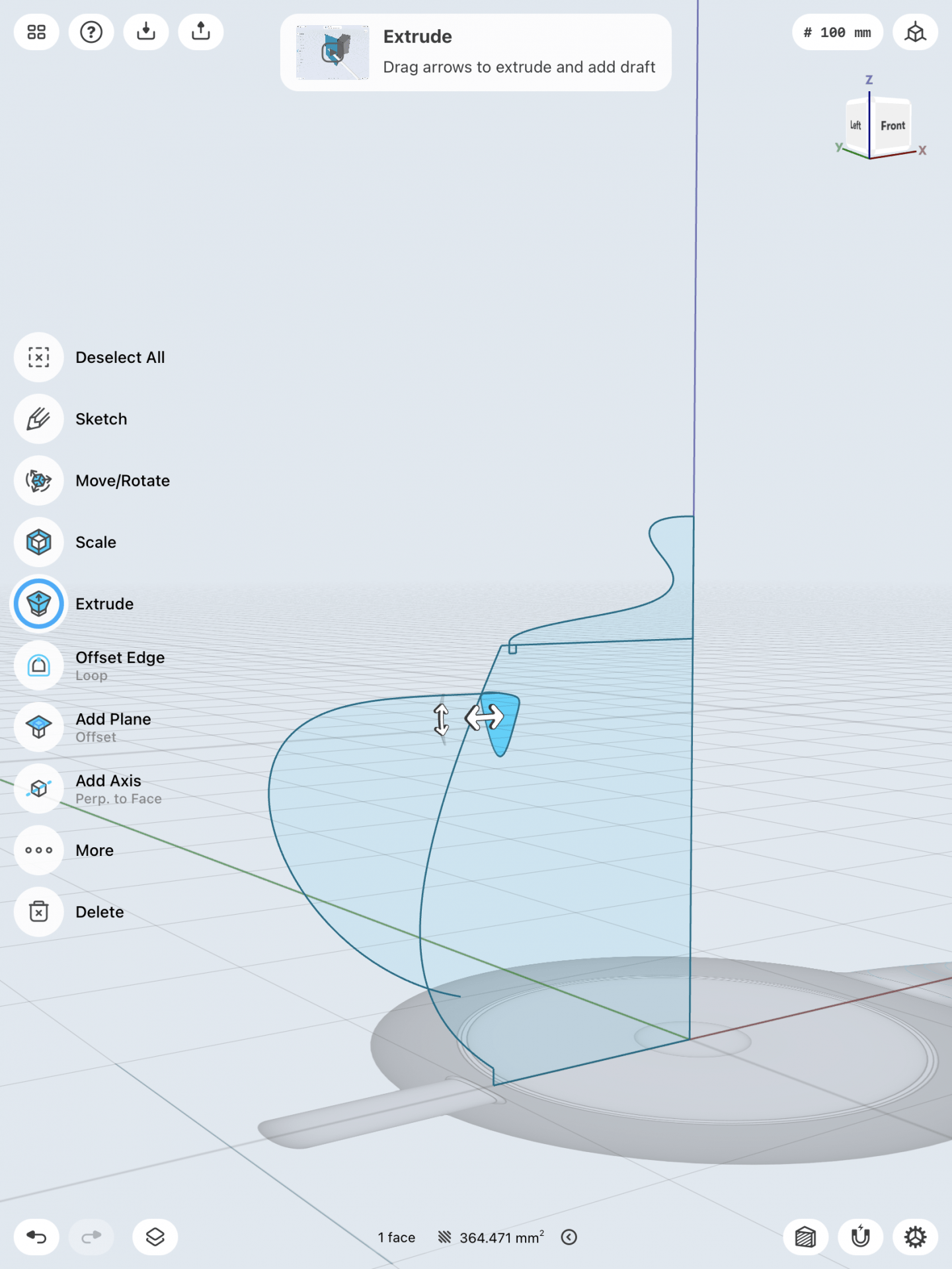
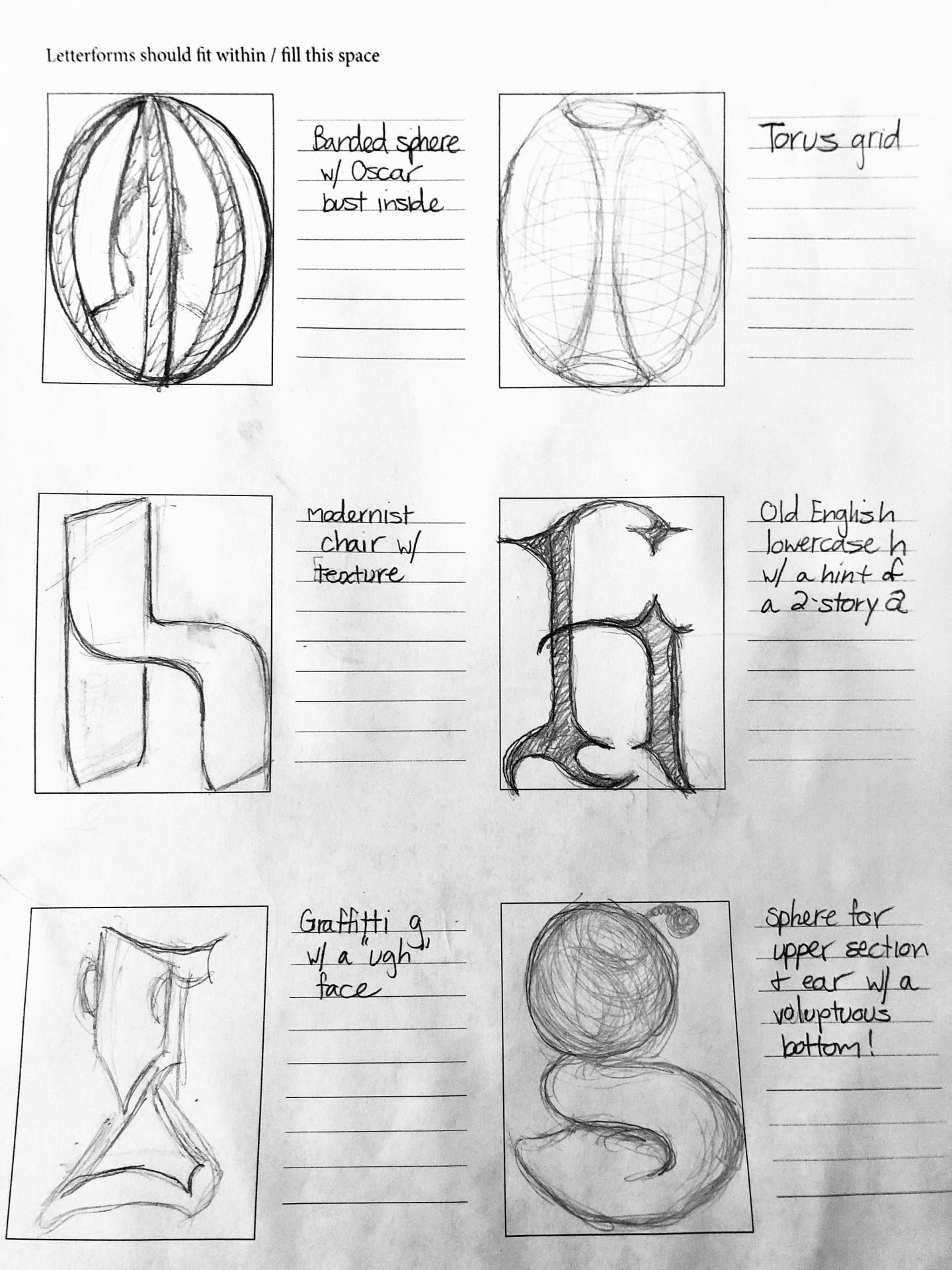
The letterform that took the most trial and error was the lowercase “g”. This glyph has so much character, I wanted to try and sculpture a two-story version in the round.

Test Prints

After modeling each letterform in Shapr3D, I test printed each on my Jellybox printer to get a sense of form but also how the models worked together. Each model took approximately 1 1/2 hours to print.

The C‘h’air felt more like a loveseat rather than a chair with the 65mm 50mm dimensions. So I’ll reduce the width to 35mm for the final print (as seen in the 3D view below).

First test print, 100% scale, coarse preset, no raft/supports, printed on side
Predetermined dimensions of 65mm x 50mm are more of a sofa than a chair.

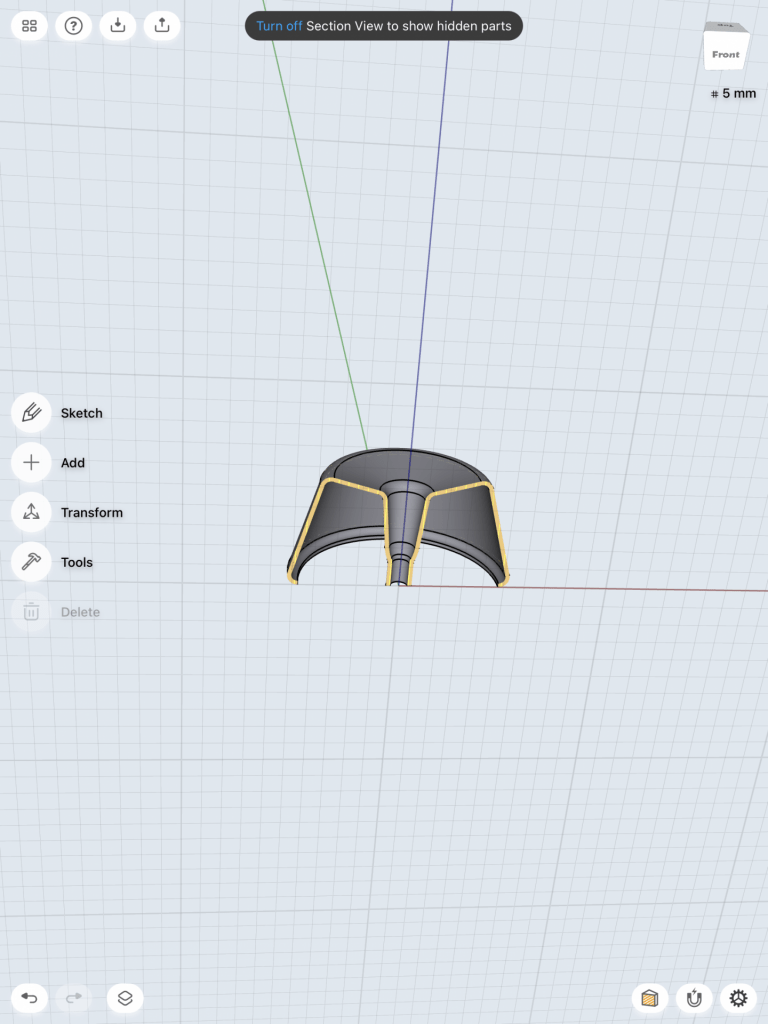
The caged Oscar test print results were better than expected. The top connections of the multiple O’s need to thicken, but overall the bust and curves held up well.

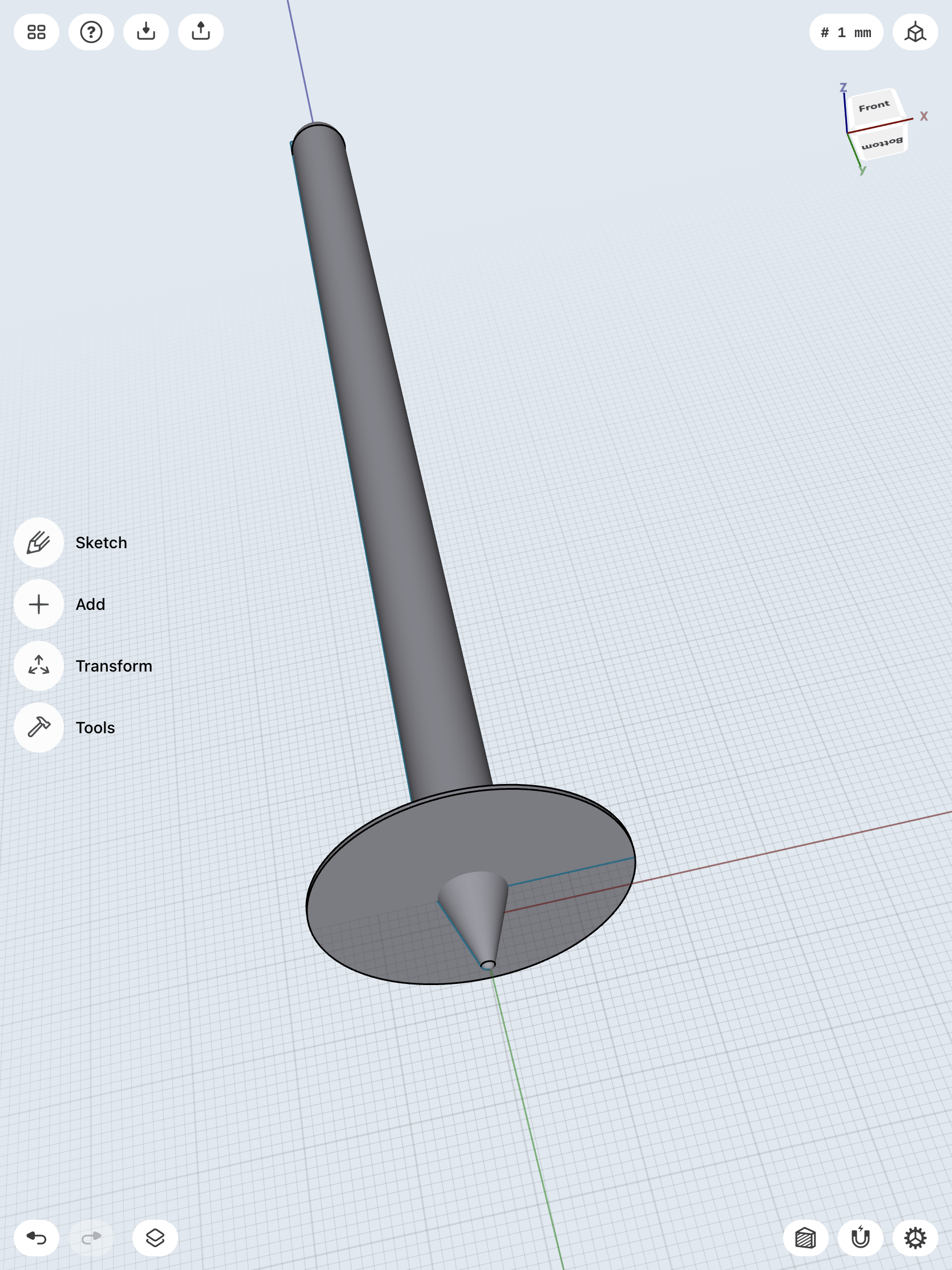
The sculptural lowercase ‘g’ is still a work in progress, but I was successful in creating the top sphere with ear and the bottom tail. I’d like to refine the connection between the two stories. The 3D view is at low resolution since Tinkercad couldn’t handle a model with more than 300,000 triangles in the mesh. Initial print 100%, coarse preset with raft and supports. The ball of the ear snapped off when removing supports and still need to remove more support material underneath the top story and in between the tail.

Timelapse of 360° view of test print. Need to flatten bottom a bit to stand upright.

Back to Top

Final Prints & Reflection

Deadlines always push the limits to what we can achieve. I attempted to print my final letterforms at home so the class could use the 3SPACE lab, but unfortunately, my Jellybox said no. With a thermal runaway error midway through the prints, I had to go into the lab.

Jellybox final prints never made it past 50% due to temperature errors.

But I would say my printing issues at home were kismet. For the first time all term, being in the lab provided that in-between time with students. It felt good to have those teachable moments again (just as much for me as them). I thoroughly enjoyed this special topics class, and I hope I can dive into the 3D relm with students another time.

Below are the final prints of my three letters: lowercase h, O/o, and lowercase g. Not sure why it took me this long to realize I chose the letterforms for “hog”. As for printing, I would like to try my c‘h’air standing upright since the side on the plate didn’t keep it’s soft edge, and my lowercase ‘g’ has been printed on its side and upright with neither keeping it’s ear. The flattening of the bottom does help it stand better, but I’m not quite satisfied with how to finish it since the supports are difficult to reach or roughs up a beautifully pristine sphere. The caged O needed a little egg top and flattening of the bottom. Overall the 360° view of the letters are where I want them to be.

Back to Top

Shapr3d First Models

Bracket

I had a lot of fun learning how to create this three hole bracket. First, I created three circles and made them all equal to each other so that the holes in in the bracket would be even. Next I had to create 3 arcs and create tangent relationships between the arcs and the circles so that they would come together as one whole unit. After removing the unnecessary lines I had the base sketch for my 3 hole bracket. I then took that base and extruded it upwards so that the 3d model would then be created. After doing that I created 3 more circles in each corner of the bracket and negatively extruded ( downwards) each one so that that I could create the holes that go within each corner of the bracket. After that I was done and all that remained was to round the edges of the 3d model to make it look nice and neat and my completed bracket was done! The images below are in chronological order. Model a Triangle-Cap

Stylus and Base

Creating the stylus and base was challenging but I still enjoyed the process and learning how to create intricate details that add to the overall look of the object. Starting out with my sketch I had to draw a pencil like shape on a 2d plane. I had to remove a section of the sharp end and add a curve to it so that when I turned the sketch into a 3d model it would have a rounded tip. Using the revolve tool I turned the 2d sketch into a 3d shape. To create the divot between the tip of the stylus and the rest of the body I created a circle that indented into the stylus and then deleted it so that only the indented space was left. The next step was to remove one edge of the stylus. I did this by creating a flat surface on the 2d plane and then extruding it upwards through the stylus. After deleting it the side that I needed to be gone was gone. To create the base was a similar process as the stylus. I drew a 2d sketch and then used the revolve tool to make it 3d. I used section view to cut the 3d model in half so that I could properly adjust the stylus in the hole of the base. I had to adjust the placement of the stylus and round the edges of the base to make it look neat and proper but after these adjustments I was done. I rounded the edges of the base on the top and bottom and my final product was complete. The images below are in chronological order. 3D Modeling a Stylus & Base on iPad | Shapr3d Step-by-Step

Shapr3D First Models

Tutorial Bracket Mount

The first model below was process of creating the bracket mount from the learning section in the Shapr3D app. It was fun learning from the tutorial of how the process of making a certain 3D model was made.

Step 1
Step 2
Step 3

The first step was to make a sketch of the main component of the bracket mount. I first sketched of the dimensions of the sizing of the model, then on the next step, I stretched out the body by 30mm and made it into a 3D figure. I then used the offset tool to measure the inside of the model and incorporated a hole inside of the model. The next step was to add the hook and the rest of the top components. I added a work plane, hovering the model to begin the next step. The images below were the next steps I have approached.

Step 4
Step 5
Step 6

The next step was working with the work plane. I combined a circle and a long rectangle into one figure and then lowered that work plane figure onto the model, so it would cut through the model, making its shape. I then intersected the two separated models together into the image shown on step 5. I then used the concentric tool to group a circle within the model as well as two more circles at the lip of the model to make its opening. The final step was to make the base of the model.

Step 7
Step 8
Final Product

I sketched out the base of the model then made it into a 3D item by making its base 50mm by 40mm in size. I then made 4 holes on the base plane and used the concentric trait to align them to each corner. I then smoothed out the edges around the 4 holes to make the function of the base more better. Now it was time to connect the two models together. I attached both of the models together and then smoothed out the edges around the model to give it a authentic look as well as changing the models color to give it a better look. In the end it turned out great, and looked exactly as the tutorial model.

3D Modeling an iPad Stylus & Mount

This model was a big challenge for me. The process of creating this model was a lot more difficult than the bracket mount. It required more steps and details to achieve its dimensions as well as the whole model itself. The process took a lot longer than I thought it would be, but all in all I was able to achieve to create an iPad stylus with a mount in it. Below are the steps that I have taken to achieve the end product.

3D Modeling a Stylus & Base on iPad | Shapr3D Step-by-Step
Step 1
Step 2
Step 3

I first sketched out the overall sizing of the iPad stylus. The height was 166mm and I sharpened the arc at the tip of the pencil to give it a better look. I then highlighted the sketch, used the extrude tool, then selected the long side of the stylus, used the rotate around axis tool, then finally used the revolve tool to make it into a stylus shape. In step 3, I added some details by combining a skinny rectangle at the side of the stylus to give it more of an iPad stylus look. The next step was to make the stylus mount.

Step 4
Step 5
Step 6
Step 7
Final Product

I went back to the 2D view of the model to create the mount for the stylus. I created the dimensions from the mount as seen above, and I then highlighted that shape, as well as highlighting the side of the long side of the pencil, and used the revolve tool to make the shape of the sketch go around the stylus. I had to make some adjustments since the pencil wasn’t completely inside of the mount, so I had to move the stylus around to fit into the mount. It fit perfectly and at the end, I curved the edges around the mount to give it a cleaner look, as well as changing the color of the stylus and the mount. This process was very challenging for me, I had to learn new types of tools that I haven’t learned before to create this model. However, I have learned a lot from these videos, and I look forward to what I will make with these skills that I have learned in Shapr3D.

Shapr3d First Models


Bracket

To being learning Shapr3D more in-depth I followed the Bracket Mount tutorial in the app. Below are pictures from beginning to end showcasing the process of the design that I made by following the tutorial.


Personal model

The tutorial I choose to follow from the Shapr3D step-by-step modeling guide to make this model was the 3D Modeling a Stylus & Base on iPad. Below are screenshots of the entire process of following the tutorial to create the design from beginning to end.


Shapr3D First Models

“Bracket”

I created the bracket mount 3D model in Shapr3D by beginning with a 2D view of the grid and drawing the initial basic structure of the body of the bracket with the line tool. I then extended or stretched the flat outline to expand it into a 3D model. I added a second plane at the top of the structure and was able to sketch the top section of the structure, also using the line tool, on the additional plane using a 2D view again. I expanded the sketch into a 3D structure and combined it with the already constructed body. I created holes in the structure by drawing additional outlines on the structure, either with the line or circle tool, and pushed the shapes through the model with the shapr arrows to a hole in that shape in the bracket. Finally, I added the base of the bracket by using the rectangle tool to create a 3D rectangular base. I added holes in the base using the circle tool to create 4 even circles in each corner of the rectangular base. To make the final model appear more smooth and complete, I selected the straight edges of the bracket and curved them, giving the object a more rounded finish.

“3D Modeling a Bench on iPad”

Similar to the bracket model, I began the bench design with a 2D view of the grid to make it easier to sketch the initial outline of the bench. I used the line tool to sketch the shape and offset the edges to increase the thickness of the bench. I extended the sketch to make it a 3D model. I selected the outward face of each side of the bench and once again had a 2D view of the surface. I created the holes in the sides of the bench by using the rectangle tool. I selected the edges of the rectangle to create a curved surface rather than a straight edge and used the arrows to push the shape through the side to create the hole. Finally, I selected the bottom edges of the bench and gave them a curved finish for a completed appearance.

I used the “3D Modeling a Bench on an iPad | Shapr3D Step-by-Step” video tutorial to create my bench model in Shapr3D.

Shapr 3D First Models

Triangle Cap

This tutorial made the construction of a triangle cap very easy and straightforward. We began by ensuring that we were in a millimeter view and that all snapping guides were on. In the top view, we made a sketch that would then become the basis for our triangle cap. Some of the functions were difficult to figure out, such as the “copy” function, because the version of Shapr3D that was used in the video is not the same as what I have on my app, but I figured these things out as we went along (the copy function is a small button that appears next to the sketch). We utilized dragging the transformation centers to the origin and rotating in order to make copies to make our sketch. We also used the equal tool to ensure that our circles stayed the same size. Drawing the arcs was a bit confusing because I thought that I had to guess where the person in the tutorial was drawing the arcs from, but in a later step he instructs to make them all tangents and set a 50mm radius, which made my sketch look like his. Once we made the sketch a body, we his the body and the sketch to begin a different part of the object. This was important for me to learn because I did not utilize this when making my first Shapr 3D sketch for the Self Expressions drafts. We drew a new sketch and used the revolve tool, which I have never used, to create an odd looking shape. Using a new plane, also something I did not do, allowed us to more easily sketch what we wanted and create the holes for the triangle cap. Trimming really helps to organize your sketch as well, as seen throughout this tutorial. The techniques used in this video were ones that I had never thought to do and will enhance future designs of mine.

Photos of the process

Tinkercad i-frame

Tutorial Reference

Model a triangle-cap from Shapr 3D

Bracket-mount

Although I do know that the bracket-mount tutorial was meant for people who could not see the trimagle cap tutorial, I really wanted to hone in on the skills and I thought this design looked intriguing and challenging. Making sure we were in millimeter view and had all on the snapping guides, we began sketching on the left view which is a 2D view, which is easier to sketch on. We manipulated the work plane so that each block represented 5mm, which was better for this design and something I had not thought about before. We drew a an oddly-shaped which we then turned into a 3D body by pulling it out. Being able to adjust the lengths by doing an action and then pressing the measurements associated with it and customizing them helped greatly throughout this entire tutorial. We used the offset tool to create a sketch on the inside of the model which we would later turn into a hole. Drawing a sketch above our work and then pulling it down later to cut parts makes the process much easier than what I had thought you would have to do. Trimming unnecessary parts of the sketches really does wonders in terms of organizing a sketch and design. What I believe this tutorial exemplified was hiding and showing bodies and sketches; in my Self Expressions Iterations I was having a lot of difficulty because my sketches and bodies were all over the place, but throught his tutorial I became aware of how to fix this issue and create a more seamless design. We used the intersect method to manipulate our design and make something that was once a hole into the body we want. Making circles concentric ensures that your sketches are right where they should be and makes them precise. Maneuvering the app was made easy with this tutorial, as every little movement was made clear and vocalized. Cutting material was made easy through taking a sketch and pushing in downwards to cut through another body.

Optimization was another area of design that this tutorial made clear of its importance. We hid our main body and began a different body. We optimized blending by selecting all of the edges we wanted to blend and doing it all at once. Again, using the copy tool, we optimized translating circles. Selecting all four circle filling and pulling them down to create holes was another way that we optimized because this allowed us to not have to do this one by one.

We opened the view of the first body again and saw how they were not one body, and were actually two separate bodies. Using the union tool, we made the two bodies into one; this really helped when it came to customizing the color because you did not have to try and find the exact same color for both parts.

We did a lot of blending in this sketch, especially towards the end. Making circles and arcs concentric also added to the precision of the design. We added a lot of details to this design which I believe makes this tutorial stand out; aesthetics really do matter in a design and this tutorial’s precision on this matter makes me want to incorporate more of these techniques into my future designs.

Photos of the Process

Tinkercad i-frame

Tutorial Reference

Model a bracket-mount from Shapr 3D

Shapr3D First Models

Bracket

My first step for the model was to draw with lines in a 2D workspace which I would then make a closed shape to stretch out the model with. This was repeated for a lot of the pieces on this model. The whole process was a lot of making shapes that I would extrude out, then fillet all the rough edges to make them rounded and smooth. This was the first model I had ever done and it looked extremely complicated at first. The guide made it really easy to follow along because he split everything into manageable parts. I learned a lot about the fillet tool which came in handy for the second model.

Bench

I followed the bench tutorial from Shapr3D for this one. I drew out a couple 2D lines, which I would link together and manually type in the angle of separation. I learned how to use the tangent tool to link the corners with rounded edges. After that, I used the offset tool to expand the line I originally drew, and connected that original with the offset line at the bottom, making a closed shape which I could stretch into a 3D model. I made some handles and filleted all of the sharp edges. At the end I decided to use the same colors as in the video.

Shapr3D First Models

Bracket

To begin learning Shapr3D more in-depth, I followed the “Model a Triangle Cap” tutorial within the app. This was very helpful in learning how to use the apple pencil to create sketches and turn them into full three-dimensional models. There were a few times where the software did not work as I was expecting, and I had to restart to get it to recognize my sketch as a closed shape. After trying again, it worked properly and I was able to finish the model.

Stylus and Base

For this model, I followed the “3D Modeling a Stylus & Base on iPad” video tutorial. I was surprised to see that the process of modeling a stylus was more complicated than I had expected, however this was likely due to the fact that I was still getting used to the software. It was very interesting learning how sketches can be revolved around an axis to quickly create a 3D shape. There were again a few places were the software was not working exactly as it was in the tutorial video, but I was able to use workarounds to achieve similar results.

Shapr3d First Models

Bracket

To create this bracket mount, the first step I took was outline the shape of the object in 2D. From following the tutorial I was able to sketch the outline of the object with the correct dimensions. After the 2D sketch was completed I selected the sketch and pulled it out to make the body 3D. After filling out the object, I then beveled the sides and created a hole inside of the bracket.

The next steps I took was to create a hole on top of the bracket by using the plane tool to place the shaped hole in correctly. I then pushed the plane down through the solid object to create a hole. I then intersected the two objects to get the correct shape of the bracket mount.

I then beveled the outside arms that were sticking out to round them out and places a hole in between the two arms.

The bottom portion of the object then needed to be made and connected. A separate square the four holes in each corner was then created. We rounded it out and then connected it to the entire object.

The final step that was taken was to bevel out the rest of the edges to perfect the bracket mount.

3D Modeling a Tea Kettle

For the 3D modeling of our choice I choose to create a tea kettle. This design was very challenging and very time consuming. To start, the first step I took was to download the tea kettle image to trace over it. I then used the spline tool to sketch half of the outline out. After sketching the outline out I revolved the 2D sketch to make it into a 3D object. I then did the same to the top of kettle pot cover. After those were fully revolved I then created the handle by creating a plane on the 2D sketch of the handle and used the sweep tool to make the handle 3D.

The next step was creating the spout by using the ellipsis tool to create circles where the spout would connect to the kettle. After placing the circles in the correct position, I clicked all the circle sketches in place and used the loft tool to make it into 3D.

I hid the kettle bottle to make sketching the spout easier but after bringing the body back, I then hollowed out the inside of both the kettle and spout by shelling the object.

Lastly, the final step I took was beveling small details and angles of the kettle. I unhid the other parts of the tea kettle and finally changed the color.

Credit to Shapr3D and tutorial by Wayne State Industrial Design Professor and Autodesk Expert Elite educator Claas Kuhnen.

Sharpr3d First Models

Bracket:

For my first model, we were instructed to create a bracket mount. This was very easy as the 2d sketch started simple and added components at a slow pace. To start, the 2d sketching was easy to do, simply apply a front facing view and draw the elbow like shape. From there, I extruded to a 3d model and added a work-plane to then add the top piece. The biggest factor that I took away is that you need to add slowly and confidently as sometimes it can get confusing. I enjoyed learning about the how the holes were added and adjusted using certain tools within shapr3d. In addition to that, the use of workplane to create the top piece of the bracket is something that I’ll make use of for future projects. As a whole, this model taught me a lot more about the program and I think the finishing touches like rounding edges and smoothing harsh points is something everyone should be knowledgeable about.

Bench:

For this model, I had a much more difficult time following the tutorial. I don’t think that this model was necessarily more difficult, but I was definitely working with a much larger piece. This model used inches as a form of measurement which worked well for the purpose. The largest issue was the curves and angle adjustments. Some tools that I learned to user were “tangent” and “horizontal.” With those, It made it to where I could adjust angles of the curves to match and move accordingly with the rest of the model. Other than those tools, the rest of the modeling process was smooth. I sketched the initial model and extruded it to be a 3d item. After applying the target and horizontal tools to the curves, I focused on the handles and followed the same process. Coloring the model was also very simple, just use the tool and double tap to add it to all or individually select.

*I’d like to note that for this model, the two shared a commonality in the tools stated above. With the tools, It made it to where I could move and change height and width, without altering the entire piece. The main piece was the bench one, but the second I chose to include as practice.

Tutorial followed: https://youtu.be/qiIV9sE1J9w