Michaela’s Story

Research & Concept

Each letterform in the English alphabet is unique, but also contains the same basic line forms and structures. Many of the letterforms are very similar to each other, such as “P” and “R”, or “O” and “Q”. These forms are only differentiated by a single slanted line placed in the form. However, when letterforms are converted from 2D to 3D images, there is a lot more room for different interpretation of the forms and unique styles to emerge.

First Glyph: “M”

The first letterform I chose was the letter “M”. I chose the letter “M” because it is the first initial in my first name, as well as my dad’s first initial. The letterform “M” is unique to me because it can have very straight, pointed edges at the top of the letter, or the edges could be curved, like arches. The typical form is straight line stems on either side of the “M” that come to a point where they meet at the top. There are many different styles of the capital form of “M” seen in various fonts.

Second Glyph: “R”

The second letterform I choose was the letter “R”. The letterform “R” has a straight stem on the left side with a curved edge on the right with an extended line. “R” has a very similar letterform to the letter “P”, with the addition of a slanted line. I choose the letter “R” to design a 3D print for because it structure and form. I prefer the capital form of the letter R to the lower case form because of the curved upper half and the line that extended from the middle to the base of the glyph.

Iterations

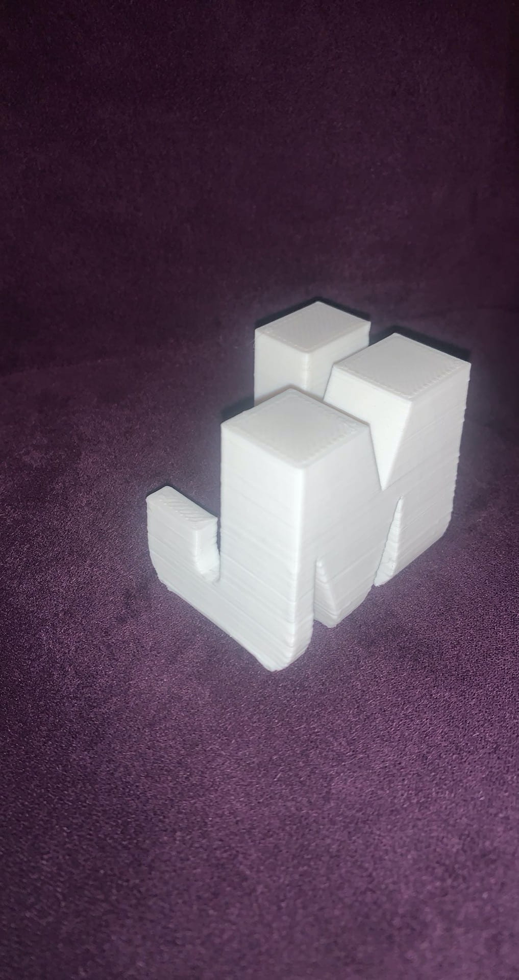
For my M letterform, I wanted to create a curved yet triangular shape for the arches in the capital M. I used two elevated 90 degree 3D triangle forms and had them intersect at one of their 45 degree angle points. I added long rectangular posts on to both outer sides of the triangles to give the form the appearance of the letter M. I used the tools in Shapr3D to blend the edges of the triangle to give them a curved, rounder shape. I also blended one side of the bottom edges of both rectangular posts to add a reverse mirroring effect to the letterform. I exported the file with my letter design from Shapr3D and imported it into Tinkercad.

After receiving feedback from my peers, I went back into Tinkercad and added semi-circular holes to the triangles forming my ‘M’ letterform. These arches in the triangle are meant to give the letterform the illusion that the lowercase form of ‘m’ is inside of the uppercase form of “M”, giving the letterform a multi-purpose.

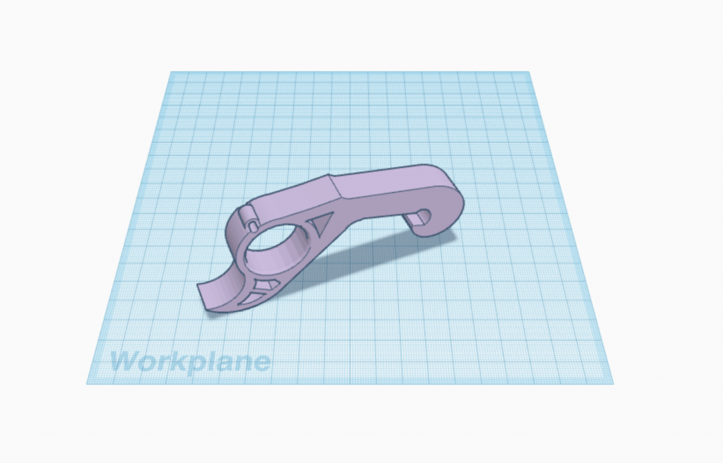
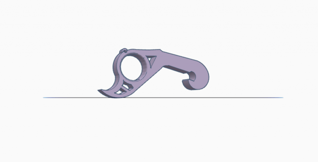
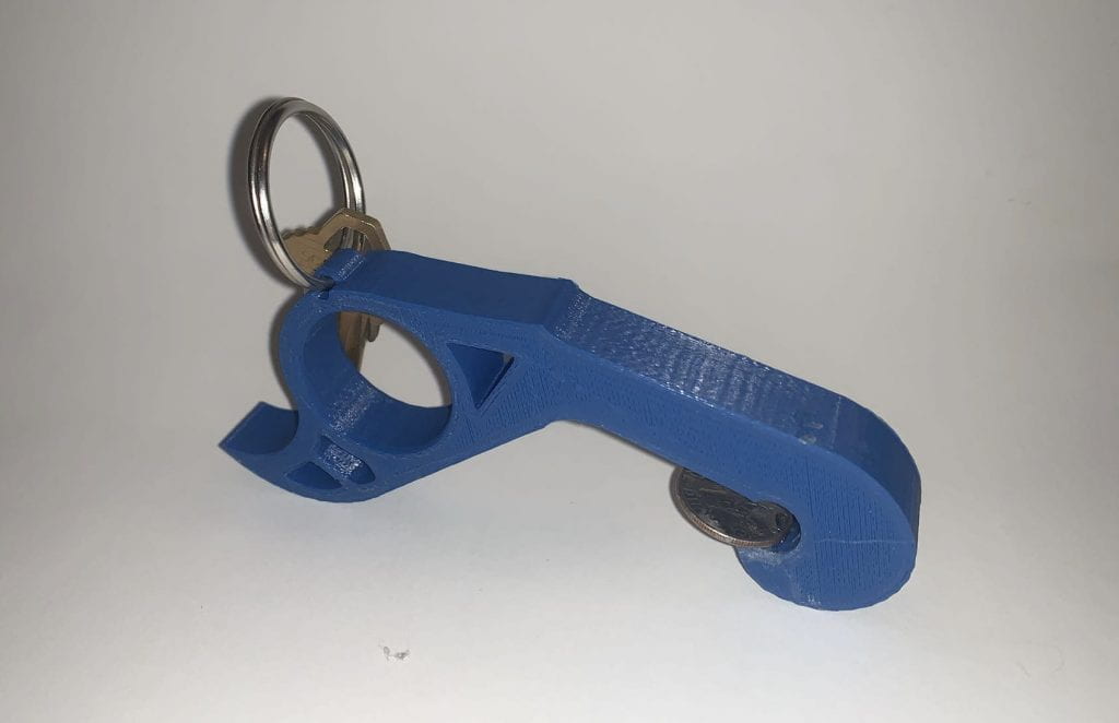
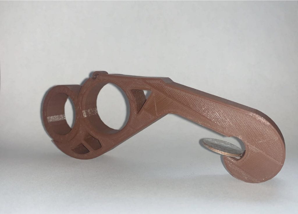
For my ‘R’ letterform, I wanted the design to appear slightly whimsical. I added a curved loop that extends upward at the end to a rectangular post to create the ‘R’. For the initial design, I used the scribble tool in Tinkercad to formulate my idea into a 3D model. I then attempted to use Shapr3D to re-create the design with the spline tool. The design on Shapr3D did not turn out the way I had envisioned it in my head and the edges were too rigid and not curved enough. I then went back into Tinkercad to smooth the edges of the ‘R’ and give it the original appearance I had hoped for.

Test Prints of ‘M’ and ‘R’ Letterforms

Final Prints

For the final print of my ‘M’ letterform, I went back into Tinkercad and added a rectangular base to the bottom of the triangle arches because in my test print, the bases of the arches were very thin and not proportionate to the rest of the letterform. I also increased the width of the letterform as a whole to increase stability when standing the 3D letterform upright. In my test print, the width was too small and the print was unable to stand properly.

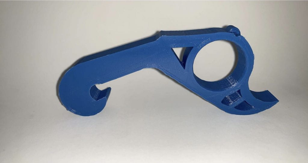
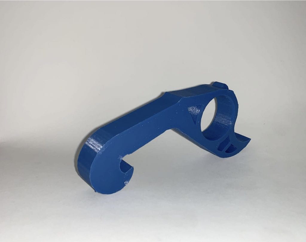
For my final print of my ‘R’ letterform, I removed the space between the body of the ‘R’ and the rectangular post. I also increased the width of the body to make the loop bigger and give the extended leg of the ‘R’ a longer, more curved length. I also added a box-like extension of the loop on the left side of the rectangular post.

Shapr3D First Models

“Bracket”

I created the bracket mount 3D model in Shapr3D by beginning with a 2D view of the grid and drawing the initial basic structure of the body of the bracket with the line tool. I then extended or stretched the flat outline to expand it into a 3D model. I added a second plane at the top of the structure and was able to sketch the top section of the structure, also using the line tool, on the additional plane using a 2D view again. I expanded the sketch into a 3D structure and combined it with the already constructed body. I created holes in the structure by drawing additional outlines on the structure, either with the line or circle tool, and pushed the shapes through the model with the shapr arrows to a hole in that shape in the bracket. Finally, I added the base of the bracket by using the rectangle tool to create a 3D rectangular base. I added holes in the base using the circle tool to create 4 even circles in each corner of the rectangular base. To make the final model appear more smooth and complete, I selected the straight edges of the bracket and curved them, giving the object a more rounded finish.

“3D Modeling a Bench on iPad”

Similar to the bracket model, I began the bench design with a 2D view of the grid to make it easier to sketch the initial outline of the bench. I used the line tool to sketch the shape and offset the edges to increase the thickness of the bench. I extended the sketch to make it a 3D model. I selected the outward face of each side of the bench and once again had a 2D view of the surface. I created the holes in the sides of the bench by using the rectangle tool. I selected the edges of the rectangle to create a curved surface rather than a straight edge and used the arrows to push the shape through the side to create the hole. Finally, I selected the bottom edges of the bench and gave them a curved finish for a completed appearance.

I used the “3D Modeling a Bench on an iPad | Shapr3D Step-by-Step” video tutorial to create my bench model in Shapr3D.

3D Scan

I created a 3D scan of myself through the Qlone 3D Scanner application by using an iPad with a Lidar camera attached to scan myself. I had to slowly rotate the camera around my subject to fully encapsulate all of the angles of my subject in the scan, especially under the chin and at the top of the head. After I was finished scanning, I saved the file as an .obj file to the iPad, and then exported the file from the iPad to my laptop by using airdrop. I opened the file on my laptop by importing it through Tinkercad where I was able to scale my model and add a base at the bottom of the model of my scan to clean up the edges and give it a more precise look.

After my model was complete in Tinkercad, I went to 3SPACE and logged into my Tinkercad account to download the .obj file onto the computer so I could upload the file into the Ultimaker application to prepare to print the model. I made the infill of the final print 20% with a 0.05 mm layer height and a raft plate adhesion.

Michaela’s Self Expression

Research & Concept

The functional form I decided to add playfulness to is an ordinary kitchen measuring cup. The original design I worked off of is measuring cups with the measurement for cups on one end, and the measurement for tablespoons and teaspoons on the other end. The measuring cups are used in the kitchen when you are cooking. They allow for you to measure the exact amount of an ingredient needed for a recipe. I knew I wanted to choose a kitchen item to inject playfulness into. When you are cooking in the kitchen, it’s always good to have fun while doing it, especially if you are cooking with kids. As a child, I always loved to cook with my mom in the kitchen, and if we had measuring cups like these it would have made it all the more fun.

I decided to add playfulness to the plain measuring cups by adding a floral appearance to the design. I added flower petals along the rim of the cup side of the measuring cups. Therefore, from a bird’s eye view, the cup itself appears as the center of the flower with the petals flaring out. I designed the tablespoon side of the measuring cup to be in the shape of a leaf, extending from the measuring cup by the handle. When all of the measuring cups are stacked on top of each other, it is meant to create a 3-dimensional flower.

Iterations

The element that worked best on the print of my floral measuring cup was the petals surrounding the edge of the cup itself. I was skeptical at first when designing this model, about the durability of the petals and whether they would fit nicely onto the rim of the cup. I used the scribble tool in Tinkercad to create a free flowing design of the petal, and then copied the design multiple times to give the array of petals the appearance of uniformity. After the print was finished, I was mostly happy with the quality of the attached petals, however I would increase the thickness of the petals in any additional re-prints I make to give them a slightly bulkier appearance. An element that did not work as well as I’d hoped on my measuring cup was the addition of the leaf-shaped teaspoon end. When designing the model, I tried extending the rectangular handle and adding a hollow leaf shape with the scribble tool. During the print, the edges became slightly warped and the hole for the teaspoon was not as defined as it should be.

After my first print, I went back into Tinkercad and made some revisions to refine the original model. I removed the block shaped bottom from under the leaf teaspoon end and I made the hole for the teaspoon larger and more defined.

Final Print

For my final print, I used Tinkercad to fix the teaspoon end of my measuring cup by removing the block base and making the edges smoother to give it a more leaf-like appearance. I also increase the size of the hole in the teaspoon. This is my final print because it incorporates everything I hoped it would when I was initially designing the measuring cup in Shape3D and Tinkercad. I printed the final model with an increased infill and a raft. I was very happy with my final print as a whole. I tested the measuring cup in my kitchen and used it to make chocolate chip cookies. The functionality was successful.

3D SVG

I chose to create a 3D model of a monogram of my initials. I’ve always wanted a monogram necklace so I figured this was the next best thing! I created my 2D monogram model in Adobe Illustrator. I started by entering a simple text box containing my typed initials in the font bondoni. I made sure my letters were appropriately sized, with the middle letter being the largest and the other letters having an equal smaller size. Then, I created an outline of the letters and proceeded to stretch the borders to form fluid connections between them. After I was finished creating my 2D model, I saved the file from Adobe as an SVG. I opened Tinkercad and imported the SVG file onto the workplane. My 2D monogram appeared as a 3D model in Tinkercad and I rotated the model until it was perpendicular to the workplane.

Michaela Sakitis’s Form|Function

F|F Research & Concept

This image from Thingiverse is of a 3D printed bottle opener. It is used to manually open glass bottles with metal caps. The small size of this bottle opener makes it convenient to travel with, as it can be made to go onto a keychain, or can simply fit right into your pocket. The bottle opener has a unique feature with a hole for your finger so the opener can be easily maneuvered to remove the bottle cap. The other side of the opener has a hooked end that goes over the bottle cap and applies pressure on it for removal. The image above displays how your hand can fit into the bottle opener and how it is used.

https://www.thingiverse.com/thing:269463

Potential improvements I might make to this bottle opener would be to add a second hole for the middle finger. I think the addition of this hole will allow for more pressure to be used to open the bottle with even more ease. It also increase the stability you would have on the bottle when opening it. I increased the length of the bottle opener slightly to accommodate for the second hole. For a personalized touch, I would add a very small hole at the top of the bottle opener to allow for it to be placed on a keychain.

F|F Iterations

The creator of this model of a 3D bottle opener is Mark Manger.

After printing the original model and testing its functionality alone, I found that my initial remix concept to add an additional finger hole made it more difficult to open a bottle rather than less. The curved open end that follows the first finger hole on the original model allows for more pressure to be exerted on the opener. That extra pressure is needed to force the cap off of the bottle. The length and infill of the remix needed to be altered more for the iteration to work properly. While the double finger hole might not have worked, I did add some additional features to the original bottle opener. I glued a coin onto the bottle opener end of the model to provide a better anchor to lift the edge of the bottle cap. I also added a keychain to the petite hole at the top of the bottle opener by expanding the hole slightly.

Final Print

For my final print of this model, I decided to re-do my original iterations with a few added changes. My original idea to add an extra finger hole was not successful at first. However, I altered the length of the bottle opener to be slightly longer and I fixed the positioning of the extra hole on Tinkercad. I downloaded the final remix as an STL file and I was able to print a working model with a larger infill of 30. These added alterations allowed my final print to function successfully. I glued a coin onto the end of the final print just like the original model.

Michaela’s First 3D Print

On Tuesday morning, I had my first experience with 3D printing. I was a little nervous going in because I had no idea what I was doing, but I was also very excited to use the 3D printer. Once I saw how everything works and got my feet under me, it was surprisingly easy to 3D print. The worst part is just waiting for the print to be complete. I decided to print the JMU cube because I thought it was a really interesting design and I wanted to watch it get created. I also wanted something to keep on my desk that not only represent my school, but commemorates my first time 3D printing as well. I cannot wait to 3D print again!

Hi, I’m Michaela Sakitis

My names is Michaela Sakitis and I am a junior creative advertising major with a minor in studio art. I would describe myself as being very creative and I love to be hands on in my creative work. I like to sketch, paint canvases, and make collages. I find it extremely relaxing and it’s a great way for me to de-stress after a long day. I also love to listen to music while I draw. It helps me get out of my own head and lose myself in what I am doing. I decided to take this class because I wanted to learn more about some of the technological aspects of creative design, specifically 3D printing. I’ve never worked with a 3D printer before and I want to become more familiar with it.

An object that best represents me is a wireless turntable because it appreciates the old while adapting to the new. I love kicking it old school and just taking a pencil to paper to sketch, no elaborate colors or intricate designs. However, I also appreciate using the new technological tools in my more complex creative work. This object relates to why I want to take this class because I cannot get into my creative mindset without starting my music first. A huge part of my creativity comes from my ability to block out the outside world, and I am able to do that best through listening to music.

As a creative type, I am a Dreamer.

You can find me online at:

https://www.tinkercad.com/users/4R5RRcjmhPe-michaela-s

https://www.thingiverse.com/michaelasakitis/designs