Sharpr3D First Models

Bracket

Upon completing this tutorial, I felt as though my understanding of Shapr3D and how the software functions were greatly deepened. It was really interesting to see how creative one can be with this software, as it offers a much wider range of design opportunities as opposed to Tinkercad. The tutorial itself was fairly easy to follow along with and provided me with certain tips and shortcuts that added ease to the entirety of the process. Just like with any new concept, it took me a little while to actually get comfortable with the software’s mechanics. The entire process made me realize that I could use Shapr3D to complete certain aspects of my ‘Self-expression’ piece that are too difficult to configure in Tinkercad.

Stylus & Base on iPad

Designing the stylus and base was much more difficult than I imagined it would be. Although the tutorial did not spare any details, it was very fast-paced and I definitely had to pause it and rewind it too many times. Despite its simplistic appearance, this design really tested my abilities and pushed me out of my comfort zone. I really feel like I have a much deeper understanding of Shapr3D after completing this tutorial. It is quite amazing that simple geometric shapes can be transformed into practical 3D objects. This tutorial definitely pushed my capabilities, but it also opened up new creative avenues as well!

Shapr3D First Models

Bracket

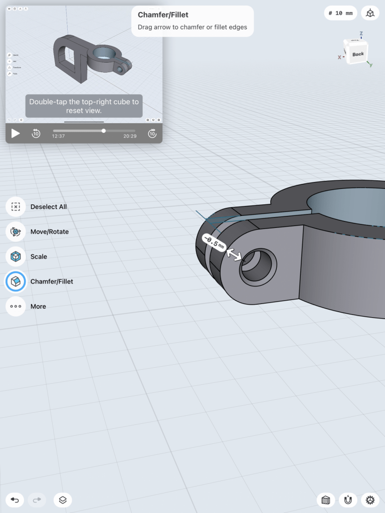
Making this bracket helped me learn a lot and was a good starting point for me while figuring out this new software. I got a feel for how to use the apple pencil and touch to effective manipulate the working planes and mess around with the various tools from sketching to chamfer and filleting as well as various planes. At one point I struggles with the chamfering towards the end of smoothing out the model. I have included screenshots of my process as well as my final model. To transfer from 2D sketches to 3D bodies, this application made it really easy. A simple tap brought the shapes into bodies.

3D Modeling a Stylus & Base on Ipad

This tutorial was a little more fast paced and not as easy to follow, but I enjoyed seeing how I turned simple triangular shapes into 3D bodies by using the revolve tool. The subtracting, locking, and chamfering tools were really helpful throughout this tutorial. Below are screenshots of my process as well as my final 3D Model.

Shapr3d First Models

Bracket

When starting the bracket mount model, the tools took some getting used to. After turning multiple 2D shapes into 3D the interface began to feel comfortable. Using the pen to create the shapes felt very comfortable compared to using a mouse on Tinkercad. I started off my creating the original 2D shape and pulling it out into a 3D form. After, began to carve out the form of the 3D model.

Bench

When beginning my the bench model sketch I was a bit nervous due to the guide seeming a bit complicated but it didn’t take long for me to get comfortable. Making the actual shapes for the model was very easy but the constraints is what caused me a bit of stress. I finished the first model pretty easily but the second bench with the newspaper holder took me a few tries. When duplicating the bench and creating the side holder I had multiple issues with fixing the constrains but after 2 attempts it came out great.

Tutorial video: https://www.youtube.com/watch?v=qiIV9sE1J9w&list=PLi4l3wxwkqyxRgcNzwMmH14JSRs6_-sMa&index=17

Shapr3D First Models

Bracket

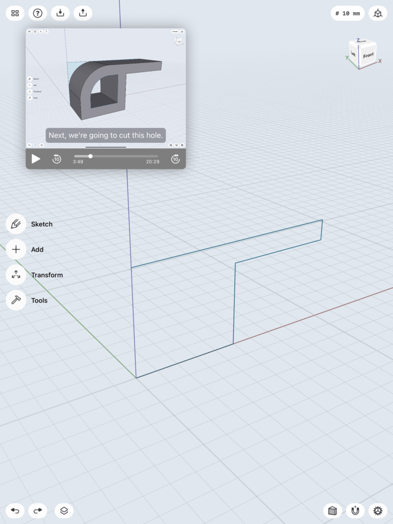
To make this bracket I first started by sketching the outline.

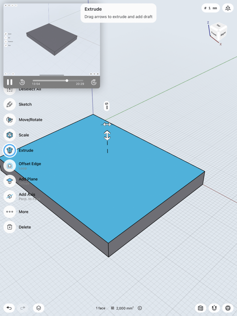
I then pulled the face of the object to make it 3D.

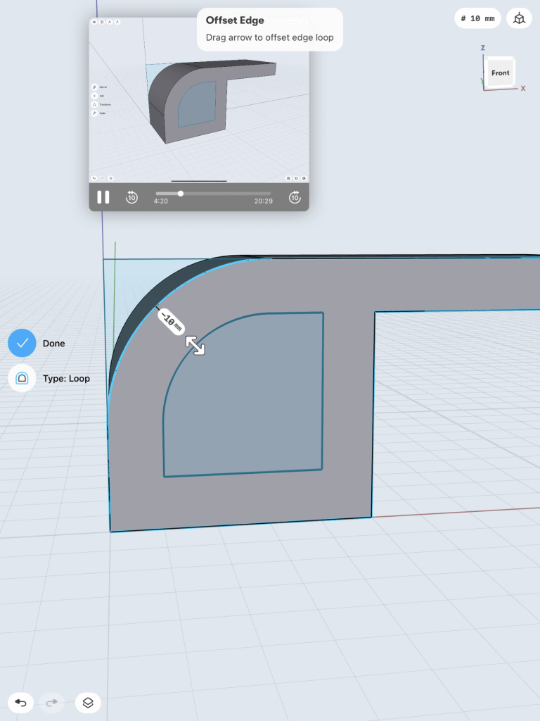
Next I needed to sketch the shape I wanted to cut out on the face of the object and then pull it through to cut it out.

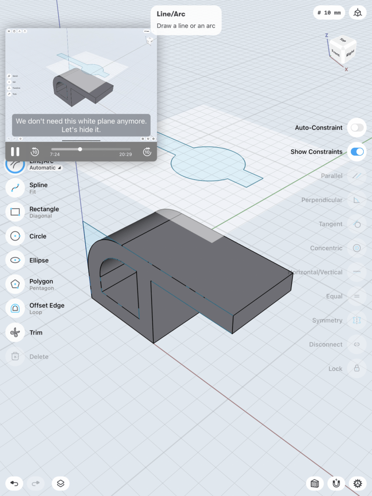
I then added a plane on top of the object so that I could sketch another shape that I needed to cut out and I used the trim tool to remove lines that I did not need.

After this I pulled that sketch through to cut the shape the way I wanted and then on the layers menu I hid all of the sketches which left me with this.

Then I sketched a circle and a rectangle and I used the co-centric tool to make the circle even in comparison to the object. I again used the trim tool to get rid of the lines within the circle. The all I did was pull the sketch through to cut it out.

I then need to fillet the edges on this to smooth them.

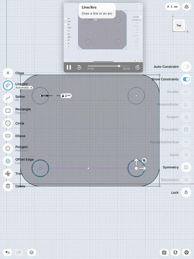
Next, I hid the body I made so I could just work on the base by making a rectangle then rounding the edges and adding 4 circles. I used the co-centric took to make sure they were aligned with each corner. Then I pulled through the faces to cut out the circles.

I unhid the body and had my final product but needed to select both body and unify them.

This was my final product! It was a lot harder than I expected and I did mess up somewhere along the way and got a flat edge along the back but it turned out okay!

Stylus

For my second model I chose the stylus tutorial and I really struggled. I actually went back and forth between a few of the tutorials and ended up on this one because I was able to get the furthest into it.

This was the initial sketch I started out with that I was then able to revolve into the stylus shape. It was so surprising to me that such a simple sketch would turn in to almost exactly what I wanted.

I was able to round the bottom but then the tutorial moved into a lot of other things and I was unable to figure out what he was doing. For some reason this tutorial was a lot harder for me to follow than the bracket tutorial.

Then I made the stand for the stylus by just sketching a shape almost like a parallelogram and then revolving it. I believe I revolved it on the wrong axis but of all the ways I tried this was the best I could get it.

Although this did not turn out the way it should I still learned a lot more than I knew even from the bracket tutorial. I am going to keep working at this in the hopes that I figure out what I did wrong.

Shapr3d First Models

Bracket

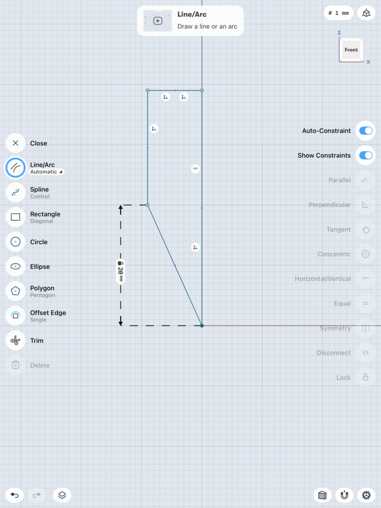
To create this bracket mount, I first needed to sketch out the very simple 2D figure. After the simple sketch was completed, I could select the sketch filling and pull it to create the body. I made the proper adjustments to the body, such as blending the edges and cutting a sketched out hole from the side.

Step 1
Step 2
Step 3

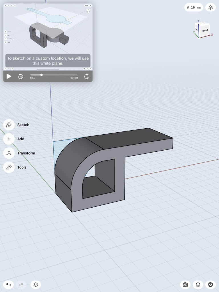
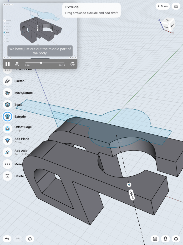
Then, I created a second sketch that would help cut out parts from the body below. I used a white plane to create this sketch on top of the body and then pushed it all they way down to cut out the middle part of the body. However, I needed to get the intersection of the body.

Step 4
Step 5
Step 6

After I intersected the these, I created another drawing of a circle on top that would eventually be cut down the body as well. Whatever circles drawn during this step were centered by hitting the concentric tool.

Step 7
Step 8
Step 9

Now I needed to create the bottom portion of the bracket mount. I began by drawing a rectangle first and pulling it out to create the base body. The edges were blended and circle holes were cut out of all four corners of the rounded rectangle. I chamfered each edge of these four circles to make it look cleaner. After I was done with the two separate bodies, they needed to be united, so I created a union between these two bodies.

Step 10
Step 11
Step 12

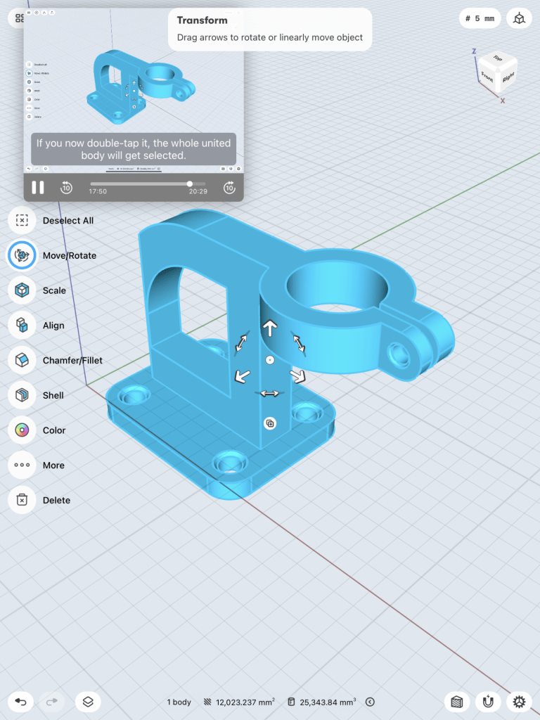
Lastly, now that I have one whole united body, I blended some more of its edges and then changed its final color.

Step 13
Step 14

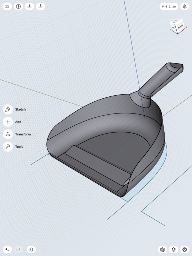
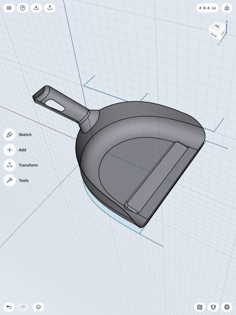
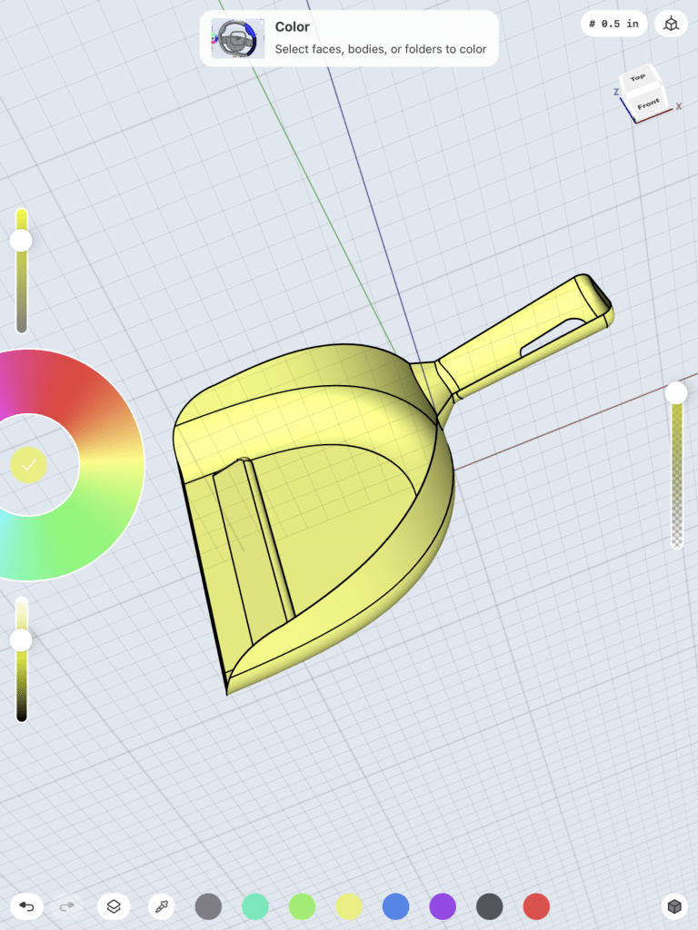
3D Modeling a Dust Pan

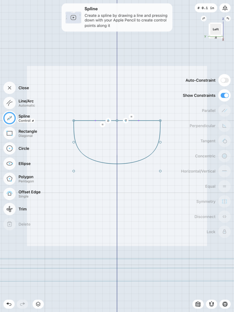
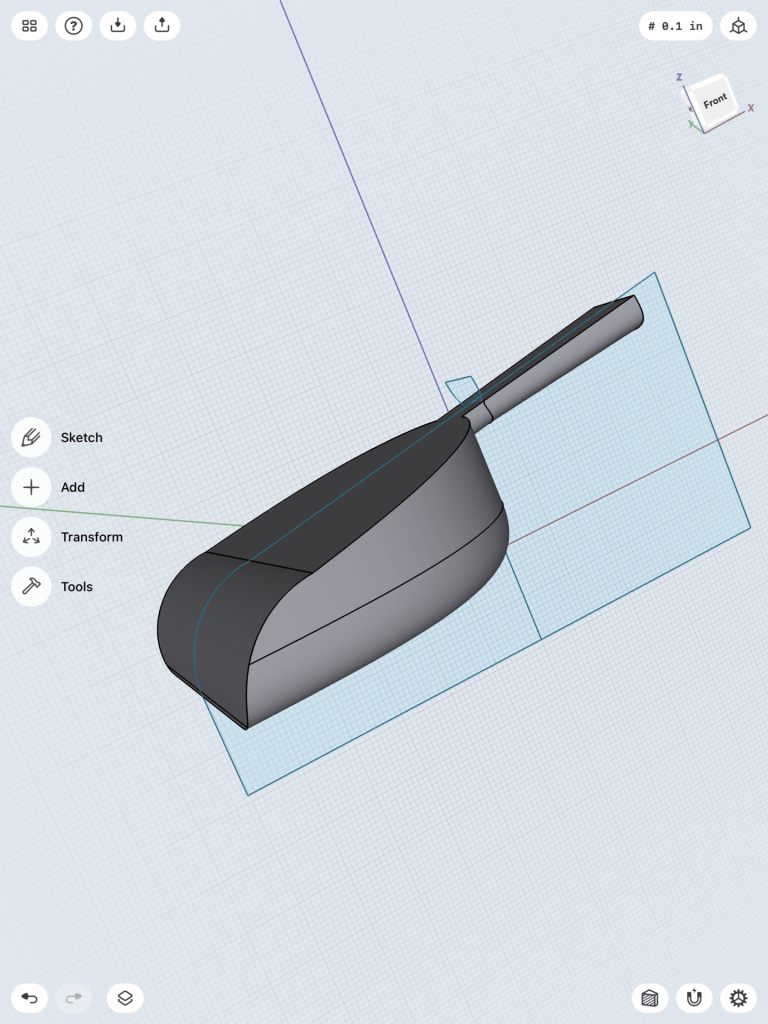
This bust pan model was much more challenging and I had difficulty getting the exact measurements of the tutorial, but it was all fairly close. I first needed to sketch out the overall dimensions of the dust pan and its handle. I was able to use the grid to create clean dimensions, and create clean arcs and splines. Once these complicated sketches were made, I could extrude everything up to create the first body of the dust pan. However to round the corner of the body in a nicer way, I needed to draw more arcs and make them tangent. I made a sweep body and performed a boolean subtract demand, which allowed for a more natural rounding.

Step 1
Step 2
Step 3

Once the main body was basically done, I could begin working on the handle by using a construction plane and splines to create the handles sketch.

Step 4
Step 5

After the handle sketch was pulled out to create a body, it needed to be attached to the other body I created by getting dragged into it. I joined these two bodies and then, rounded some of its edges on the handle. I created an outer shelling into the now conjoined body, which made the overall dust pan. I sketched out another shape that was subtracted from the other body in order to add a better function to the dust pan (shown in step 8).

Step 6
Step 7
Step 8

Lastly, I sketched out a hole for the handle by using a construction plane that was viewed at an angle. Finally, I completed my dust pan and changed the entire color of it to yellow!

Step 9
Step 10

3D Scan

I created my 3D bust scan in class, working with a group of 3 other students to get a sufficient 3D scan using a variety of formats. We took turns using the LiDAR camera attachment on an iPad paired with the Monocle Structure Scanner applicationĀ to scan each other, and while we tried the ScandyPro phone application, I found that the LiDAR attachment worked the best. None of us could manage to get the color on the scan to come out well, even after the LiDAR cameras were reconfigured. I had to stand completely still as a classmate circled me, capturing pictures of me of all angles. It took a few tries to perfect because my height made it hard for people to reach overtop of me and so my scans kept having holes at the top of my head, but eventually I got a scan that captured a perfect shape of me, not missing any areas or details, although the colors were not great.

The Monocle Structure Scanner applicationĀ captured a series of images that configure into an .OBJ file, of which I Airdropped to my computer. Once on my computer, I used Tinkercad to increase the measurements to 42.0 x 53.0 x 24.0 mm and make other adjustments including adding a block to the bottom of the bust to give it a stronger base and a hole at the bottom to get rid of the extra pieces. From Tinkercad, I then exported the file as an .stl and opened it into Shapr3D where I adjusted the layer height to 0.5mm, infill density to 20%, and the plate adhesion to raft.

The process of creating the 3D scan took some work and a fair amount of trial and error, while putting it in Tinkercad, Shapr3D, and then finally printing the 3D bust was pretty simple once I realized what I needed to do to make it print in the best way possible.

Unfortunately, I unknowingly printed my 3D bust on a broken printer, so the back half of my 3D printed bust is very stringy and disorderly, and the front seems like the adhesion was messed up too. Because of this, I would say that my 3D printed bust did not come out as great as I hoped; overall the bust is very chaotic looking and the integrity of the design did not carry over. No amount of filing would help the look of this print because the filament is not connected, so it would all fall apart more than it already is.

3D Scan within Monocle Structure Scanner

3D Bust in Tinkercad

3D Scan

The first part of this project required me to have a classmate take a 360-degree scan of my bust. A LiDAR camera on an iPad paired with the Monocle Structure Scanner application was used to complete this step. Although the scanning process required a few trials runs, professor Hooker’s comprehensive explanation and demonstration on how to use the software allowed us to complete this step without any major problems.

The Monocle Structure Scanner was able to created a 3D model by compiling multiple photos, which it transformed into an .OBJ file. Below is a picture of what the scanning software’s interface looked like. In the upper left hand corner are the dimensions of the scan. I then proceeded to airdrop the file onto my laptop from the iPad and then transformed it to an .STL file in Tinkercad, in order to make any necessary edits. Thankfully I did not need to make any major transformations to the file. I merely scaled down the bust and used the hole shape to remove extraneous pieces.

All in all, it was not a very complicated process. I was able to gain a much better understanding of how 3D scanned objects can be translated into 3D printing software. After I finished making the necessary edits to my .STL file in Tinkercad, I printed my model with little to no problems!